Microwaves Trainer (DL MICROWAVE-2.0)
PL-123010
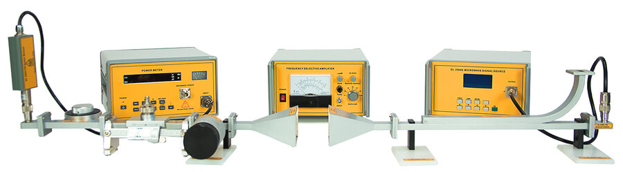
The trainer DL MICROWAVE-2.0 has been designed to introduce students to microwave technology. It consists of a set of components, accessories and instruments and can be used as a laboratory test bench to experiment with the microwaves components as well as to study the aspects of wave propagation.
The didactic approach of this trainer is to investigate behavior and to prove the physical concepts related to microwave engineering. The microwave technique, as a subdomain of electronics, presents particularities both in theoretical methods and in the experimental apparatuses and procedures used.
For this reason, in a microwave laboratory, besides general-purpose electronic devices, there are also specific devices needed to measure signals and microwave networks. The components of this trainer are easy to install, using screws, nuts and supporting waveguides.
Our 3 cm. waveguide trainer provides users with in-depth training on frequency transmission characteristics and gives students the possibility to perform all the main exercises in this field. The trainer is provided complete with a detailed educational manual.
Operating frequency: 8.2 ÷ 12 GHz.
- The trainer has been designed to start with a few related concepts providing in-depth coverage of the basic topics related to the propagation of the microwaves through rectangular metal guides.
- As an open system, multiple components can be chosen to form a customized transmission system freely.
- The trainer includes a detailed didactic manual.
COMPONENTS INCLUDED
The microwave trainer consists of a set of components, accessories and instruments. It can be used as a laboratory test bench to experiment with the components of the microwave as well as to study the aspects of wave propagation.
The trainer includes the following:
- 1 Power meter
- 1 SWR METER
- 1 Function Generator
- 1 Frequency Meter
- 1 Variable Attenuator
- 1 Slotted line
- 1 Hybrid Tee
- 2 Crystal Detector
- 1 Waveguide
- 2 Matched Termination
- 1 Slide Screw Tuner
- 2 Horn Antenna
- 2 Coaxial Adapter
- 1 Fixed Attenuator 6dB
- 1 Directional Coupler
- 4 Waveguide Stands 1 support
- 2 Waveguide Stands 2 support
- 1 Shorting plate
- 1 Reflecting plate
- 1 set Screws and nuts
- 1 set Tools
DIDACTIC EXPERIENCE
- Propagation modes, wavelength and phase velocity in a waveguide.
- Q and bandwidth of a resonance cavity.
- Power measurement.
- Standing wave ratio (SWR) measurement.
- Impedance measurement.
- Basic properties of a directional coupler.
- Attenuation measurement.
- Study of a waveguide Hybrid-T.
EXPERIMENTS DESCRIPTION
1. Measurement of the attenuation in a microwave system The measurement of the microwave attenuation is a rather complex subject. However, the first experiment will help you become familiar with the trainer. With this experiment, you will also learn to calibrate and to read the measuring instruments correctly. The step-by-step procedure will show how to measure the microwave power signal and how it is affected by different types of attenuators.
2. Crystal detector You will learn about the basics of the crystal detector, including the crystal detector circuit, the characteristics of the crystal detector, and the characteristics of the square law of a crystal detector. The square law characteristic means that the output voltage is proportional to the square of the input voltage in the first experiment the microwave source and the power meter are used, in this experiment, the SWR meter is used. You will see how easy it is to set up the microwave source to generate a modulated signal that will be applied to the crystal detector. The crystal detector output signal will be measured with the SWR meter.
3. Propagation modes, wavelength and phase velocity in the waveguide You will gain knowledge about the propagation modes, the cut-off frequency of the waveguide, the guide wavelength, the phase velocity, the group velocity, and the propagation constant. The students can very easily calculate the wavelength of the TE10 as the dominant mode of a rectangular waveguide. In addition, the wavelength can be measured experimentally using the slotted line included in the trainer.
4. Determining the Quality Factor and Bandwidth of a Resonance Cavity To be able to study the frequency meter, first, you need to understand that it has the same behaviour as a microwave resonance cavity. The cavity is a metal box with a cylindrical shape attached to a waveguide and has a simplified scale ruler to measure the frequency. Following an easy procedure, the students will measure the power drop in the cavity and identify the corresponding frequency. It is then very easy to calculate the quality factor and bandwidth of a resonance cavity.
5.Power measurement and transmission losses in microwaves systems The major issue in microwaves systems is the losses that occur during the transmission. This experiment will show how impedance mismatch will influence the reflection of the signal. The impedance mismatch will be created using the slide screw tuner included in the trainer. The major objective of this experiment is the calculation of the return loss and mismatch loss.
6. Measuring the standing wave ratio and reflection coefficient in microwave systems Because it is easier to detect the voltage standing waves, the term VSWR is more often used then SWR, especially within radio frequency (RF) systems. But what does it SWR mean? Following this experiment, you will understand what SWR is and how it can be measured or calculated. To determine how much of the signal propagating on a waveguide is reflected to the source, you will learn how to calculate the reflection coefficient (Γ).
7. Determining the waveguide impedance using the Smith chart In this experiment, you will use your accumulated knowledge regarding the standing waves (from the previous experiments) to determine the impedance of a waveguide mismatched terminating line. We can call this experiment “understanding Smith chart by experimenting” where you to read the standing waves using the slotted waveguide line, and to determine the impedance of the unknown load using the slide screw tuner.
8. Study the characteristics of directional coupler How to determine the characteristics used to define the performance of a directional coupler? You will be able to respond to this question after performing this experiment where you calculate the coupling coefficient, the insertion loss, and the directivity of a directional coupler.
9. The study of the isolation and coupling coefficient in a Hybrid Tee Working with this module gives the basic know-how regarding you will learn about the insulation and coupling coefficient of a Hybrid T. First, the student will measure the input power as a reference power of the Hybrid Tee. By measuring the E-arm power and H-arm power, you will be able to calculate the isolation factor (I) and coupling factor (C).
10.Microwave communication using a horn antenna system Students will perform a practical study of horn antenna for the transmission and reception of a microwave signal in free space. The microwave signal used in the previous experiments has now been adapted and sent to in free space by using a specific antenna – the horn antenna. The radiation pattern of a horn antenna will be plotted based on the propagation microwaves in the free space.
OPTIONAL VERSION WITH SOFTWARE
DL MICROWAVE-2.0SW
This trainer can also be supplied in another version DL MICROWAVE-2.0SW including a software and a device that replaces some modules of the previous version and especially instruments such as function generator, power meter, and SWR meter.
In this case, this version will include the following elements:
- 1 Microwave comprehensive tester
- 1 Frequency Meter
- 1 Variable Attenuator
- 1 Slotted line
- 1 Hybrid Tee
- 2 Crystal Detector
- 1 Waveguide
- 2 Matched Termination
- 1 Slide Screw Tuner
- 2 Horn Antenna
- 2 Coaxial Adapter
- 1 Fixed Attenuator 6dB
- 1 Directional Coupler
- 4 Waveguide Stands 1 support
- 2 Waveguide Stands 2 support
- 1 Shorting plate
- 1 Reflecting plate
- 1 set Screws and nuts
- 1 set Tools
The main unit adopts a 15 inch LCD display and a Windows operating system. It supports keyboard and mouse operations and can be connected to the internet for remote file transfer and browsing of related resource libraries and can also copy files to install commonly used software.
It has 2 USB interfaces, 1 LAN interface, and 1 HDMI interface to support connection with the projection device, making it convenient for demonstration and teaching.
The system includes microwave signal source, power meter, frequency selective amplifier, human-machine interaction system (microwave signal source, power meter). The software operation interface can touch and adjust the source parameters and collect power meter data.
What is this?
These percentage scores are an average of 0 user reviews. To get more into detail, see each review and comments as per below
If you have used this product, support the community by submitting your review


")
