Pneumatic and Electro-Pneumatic Application
INTRODUCTION
Pneumatics is the technology that employs the properties of gases as a way of energy transmission for the operation of devices. It offers a technological alternative in industry, presenting easy-to-regulate pneumatic circuits that operate at high speeds.
This technology is one of the most widely used in industrial automation, due to the advantages that it provides in a work environment.
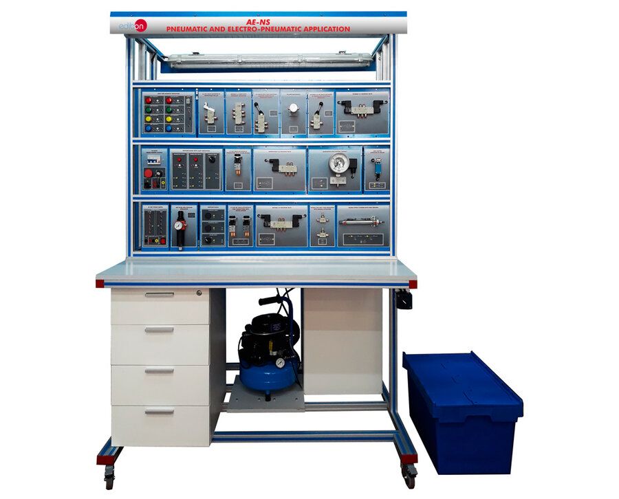
The Pneumatic and Electro-Pneumatic Application, “AE-NS”, has been designed by EDIBON to obtain the necessary knowledge to understand the operation of the most common elements used in pneumatics and electro-pneumatics.
The application “AE-NS” includes a set of practical exercises through which the students will understand how to work with the most common elements used in a pneumatic and electro-pneumatic system.
GENERAL DESCRIPTIONPneumatic and Electro-Pneumatic Application
The Pneumatic and Electro-Pneumatic Application, “AE-NS”, is a modular application consisting of a great variety of optional kits and elements to configure the desired Pneumatic and Electro-Pneumatic trainer. The optional pneumatic kits available with the application, offers the necessary elements to perform a complete study of management and utilization of the actual industry pneumatic circuits. In the following lines there is a brief description of the objective to all pneumatic optional kits:
PK-K0, Kit to study the pneumatics fundamentals: contain the components to understand the fundamentals concepts of the pneumatics circuits.
PK-K1, Pneumatics kit: contain the components to understand the fundamentals and advanced concepts of the pneumatics circuits.
PK-K2, Electro-Pneumatics kit: contain the components to understand the fundamentals and advanced concepts of the electro-pneumatics circuits.
PK-K3, Pneumatics Actuators kit: is designed to teach the concepts behind the most common pneumatic actuators as rotary motors.
PK-K4, Measurement and Proportional Control in Pneumatics kit: is a computer controlled kit, configured to perform the analog signal and the proportional control over the pneumatic actuators to implement a PID control from the computer.
PK-K5, Vacuum Technology kit: is designed to teach the most common components of the vacuum circuits, the PK-K5 include several types of cups to study the differences between them.
PK-K6, Pneumatics and Electro-Pneumatic Troubleshooting kit: is a kit of defective pneumatic components designed to teach the students the most common problem in pneumatic components, how to find them and detect the problems.
The EDIBON PLC unit is designed to work with the PK-K2 kits, and in conjunction offers the components to perform a complete understanding of pneumatic and electro-pneumatic technology with a PLC control of the pneumatic components, adding more practical possibilities to the unit.
There is available the optional elements of Silent Air Compressor, “SAC”, that provide the air flow and the pressure needed to the correct working of the unit, the Workbenches to work at one or two sides, etc.
EXERCISES AND PRACTICAL POSSIBILITIES
PK-K0, Kit to study the pneumatics fundamentals.
1.- Identification of elements.
2.- Air compression and treatment.
3.- Operation of valves with manual activation.
4.- Activation of a simple effect cylinder.
5.- Activation of a simple effect cylinder from several points (“OR” valve).
6.- Simultaneous activation of a simple effect cylinder (“AND” valve).
7.- Indirect activation of a simple effect cylinder.
PK-K1, Pneumatics kit.
8.- Identification of elements.
9.- Air compression and treatment.
10.- Operation of valves with manual activation.
11.- Activation of a simple effect cylinder.
12.- Activation of a simple effect cylinder from several points (“OR” valve).
13.- Simultaneous activation of a simple effect cylinder (“AND” valve).
14.- Ejector function and study of the venture principle.
15.- Using the ejector and suction cup to grip workpieces.
16.- Indirect activation of a simple effect cylinder.
17.- Activation of a double effect cylinder.
18.- Indirect activation of a double effect cylinder.
19.- Semi-automatic activation of a double effect cylinder.
20.- Speed adjustment of a double effect cylinder.
21.- Automatic activation of a double effect cylinder.
22.- Timer controlled activation of a double effect cylinder.
23.- Accelerated return of a double effect cylinder.
24.- Pneumatic system with emergency pushbutton.
25.- Activation of a simple effect cylinder by three pneumatic signals.
26.- Configuration of an adjustable sequence valve.
PK-K2, Electro-Pneumatics kit.
27.- Identification of elements.
28.- Air compression and treatment.
29.- Activation of a simple effect cylinder.
30.- Activation of a double effect cylinder.
31.- Speed adjustment of a double effect cylinder.
32.- Electro-pneumatic control by a monostable 3/2 NC solenoid valve.
33.- Electro-pneumatic control by monostable 3/2 and 5/2 solenoid valves.
34.- Electro-pneumatic control by a bistable 5/2 solenoid valve.
35.- Control of a double effect cylinder using Reed sensors.
36.- Automatic activation of cylinders (sequence A+B+A-B-).
37.- Operation of a pressure switch and a manometer with electric contact.
PK-K3, Pneumatics Actuators kit.
38.- Identification of elements.
39.- Activation of a pneumatic linear actuator.
40.- Activation of a pneumatic rotary actuator.
41.- Activation of a pneumatic artificial muscle.
42.- Use the function generator to set the speed of the linear actuator.
43.- Use the function generator to set the speed of the rotary actuator.
44.- Use the function generator to set the speed of the pneumatic artificial muscle.
45.- Uses of different loads with a linear actuator and observe the response.
46.- Uses of different loads with a rotary actuator and observe the response.
47.- Uses of different loads with a pneumatic artificial muscle and observe the response.
48.- Comparison between the different actuators.
PK-K4, Measurement and Proportional Control in Pneumatics kit.
49.- Familiarization with data acquisition and processing of system signals from PC.
50.- Operation of the Background suppression photoelectric sensor from PC.
51.- Operation of the Polarized retroreflective photoelectric sensor from PC.
52.- Operation of the Diffuse-reflective photoelectric sensor from PC.
53.- Operation of the Fiber optic photoelectric sensor from PC.
54.- Proportional manual control of a proportional valve from PC.
55.- Analog measurement of pressure level from PC.
56.- Analog measurement of flow level from PC.
57.- PID control loop of the flow level from PC.
58.- Analog position sensor of the pneumatic linear actuator from PC.
59.- PID control loop of the position of a pneumatic linear actuator from PC.
PK-K5, Vaccum Technology kit.
60.- Familiarization with the vacuum components.
61.- Ejector function and study of the venture principle.
62.- Using the ejector and suction cup to grip workpieces.
63.- Measure of the negative pressure level.
64.- Regulation of the negative pressure of the vacuum circuit.
65.- Differences between the suction cups of the unit, and comparison of its performance.
PK-K6, Pneumatics and Electro-Pneumatic Troubleshooting kit.
66.- Familiarization with most common failures of the pneumatic components.
67.- Study a faulty air filter and pressure regulator with manometer.
68.- Study a faulty manometer.
69.- Study a faulty air pressure tank.
70.- Study a faulty monostable 3/2 NC valve activated by a pushbutton.
71.- Study a faulty double acting cylinder with Reed sensors.
72.- Study a faulty bistable 5/2 valves with pneumatic activation.
73.- Study a faulty 5/3 closed center valve with pneumatic activation.
74.- Study a faulty vacuum pad with ejector.
75.- Study a faulty silencer for 6 mm tubing.
AE-PLC-PAN-UB (also available with others PLCmanufacturers):
The practices available with the PK-K2 are:
76.- Activation of a simple effect cylinder with PLC.
77.- Activation of a double effect cylinder with PLC.
78.- Electro-pneumatic control by a monostable 3/2 NC solenoid valve activated from PLC.
79.- Electro-pneumatic control by monostable 3/2 and 5/2 solenoid valve activated from PLC.
80.- Electro-pneumatic control by a bistable 5/2 solenoid valve activated from PLC.
81.- Pressure control with PLC.
82.- Position control of a double effect cylinder using Reed sensors and a PLC.
83.- Creation a pneumatic sequence with the PLC.
The practices available with the AE-PLC-PAN-UB working alone are:
84.- Using variables.
85.- Using digital inputs I.
86.- Using digital inputs II.
87.- Testing digital inputs (PLC-PAN-K1).
88.- Using digital outputs.
89.- Testing digital outputs.
90.- Using analog signals I (PLC-PAN-K1 and PLC-PAN-K2).
91.- Using analog signals II (PLC-PAN-K1 and PLC-PAN-K2).
92.- Square wave generator.
93.- HMI simple program (PLC-PAN-K3 or PLC-PAN-K4).
94.- Using digital outputs with HMI device I (PLC-PAN-K3 or PLCPAN-K4).
95.- Using digital outputs with HMI device II (PLC-PAN-K3 or PLCPAN-K4).
96.- Reading data from a register with the HMI device (PLCPAN-K3 or PLC-PAN-K4).
97.- Writing data to a register with the HMI device (PLC-PAN-K3 or PLC-PAN-K4).
98.- Switching screens of the HMI device (PLC-PAN-K3 or PLCPAN-K4).
99.- Internet connection of the PLC unit (PLC-PAN-K5).
100.- Control digital inputs with a web server application (PLCPAN-K5).
101.- Control digital outputs with a web server application (PLCPAN-K5).
102.- Control analog inputs with a web server application (PLCPAN-K5).
103.- Control analog outputs with a web server application (PLCPAN-K5).
All the pneumatic components of the AE-NS unit:
Work with a working air pressure of 4 bar.
The components include Quick-Fitting connectors with Built-in Stop Mechanism for 6 mm tubing.
Are attached to a screen printed metallic plate with the name and the standard symbol of the component. These metallic plates are designed to be placed on the EDIBON workbenches.
Optional kits of Pneumatic components:
• PK-K0, Kit to study the pneumatics fundamentals:
Air treatment components:
Air filter and pressure regulator with manometer:
Air filter with water trap.
Pressure regulator from 0 to 12 bar.
Double scale manometer: bar and Psi (0-12 bar).
Discharge valve.
Shut off valve.
Manual operated valves:
Monostable 3/2 NC valve activated by a pushbutton (2 units):
Mechanical activation by pushbutton.
Two NC valves with spring return.
Maximum pressure: 10 bar.
Double monostable 3/2 NO and NC valves activated by push-button:
Mechanical activation by pushbutton.
NO valve with spring return.
NC valve with spring return.
Maximum pressure: 10 bar.
Bistable 3/2 valve with hand lever:
Mechanical activation by hand lever.
Lever detent.
Maximum pressure: 10 bar.
Bistable 5/2 valve with hand lever:
Mechanical activation by hand lever.
Lever detent.
Maximum pressure: 10 bar.
Double one-way flow regulator valve:
Manual activation by a rotary handle.
2 flow regulator valves.
Check valve in one direction.
Maximum pressure: 10 bar.
Pneumatic operated valves:
Monostable 5/2 valve with pneumatic activation:
Pneumatic activation.
Spring return.
Maximum pressure: 10 bar.
Double monostable 3/2 NO and NC valves with pneumatic activation:
Pneumatic activation.
NO valve with spring return.
NC valve with spring return.
Maximum pressure: 10 bar.
“OR” valve:
“OR” valve.
Logic function “OR”.
Maximum pressure: 8 bar.
“AND” valve:
AND” valve.
Logic function “AND”.
Maximum pressure: 8 bar.
Pneumatic actuators:
Single acting cylinder:
Stainless steel.
Spring return.
Normally returned rod.
Maximum pressure: 10 bar.
Stroke of 100 mm.
Accessories:
25 meters of blue polyurethane flexible 6 mm tubing.
25 meters of red polyurethane flexible 6 mm tubing.
25 meters of transparent polyurethane flexible 6 mm tubing.
Tube-cutter for 6 mm tubing.
Tube-extractor for 6 mm tubing.
Set of 20 sealing plugs for 6 mm tubing.
Set of 20 “T” type push-in fittings for 6 mm tubing.
Set of 20 “Y” type push-in fittings for 6 mm tubing.
In-line check valve for 6 mm tubing.
Set of 10 silencers for 6 mm tubing.
Hard plastic box to keep the pneumatic elements of the unit:
Polypropylene.
Capacity: 58 l.
Lid attached to the box.
• PK-K1, Pneumatics kit:
Air treatment components:
Air filter and pressure regulator with manometer:
Air filter with water trap.
Pressure regulator from 0 to 12 bar.
Double scale manometer: bar and Psi (0-12 bar).
Discharge valve.
Shut off valve.
Air pressure regulator with manometer:
Pressure regulator from 0 to 12 bar.
Double scale manometer: bar and Psi (0-12 bar).
Shut off valve.
Manometers (2 units):
Double scale manometer: bar and Psi (0-12 bar).
8-Way manifold.
Quick exhaust valve.
Manual operated valves:
Double monostable 3/2 NC valve activated by a push-button (2 units):
2 Normally Closed valves with spring return.
Maximum pressure: 10 bar.
Double monostable 3/2 NO valve activated by a push-button:
2 Normally Open valves with spring return.
Maximum pressure: 10 bar.
Monostable 5/2 valve activated by a push-button:
2 Normally Open valves with spring return.
Maximum pressure: 10 bar.
Bistable 3/2 NO valve activated by emergency mushroom-head pushbutton:
Emergency mushroom pushbutton.
Normally Open valve.
Maximum pressure: 10 bar.
Monostable 3/2 NC valve activated by roller:
Mechanical activation by roller.
Normally Closed valve with spring return.
Maximum pressure: 10 bar.
Monostable 3/2 NC valve activated by retractable roller:
Mechanical activation by retractable roller.
Normally Closed valve with spring return.
Maximum pressure: 10 bar.
Monostable 3/2 NC valve with hand lever:
Mechanical activation by hand lever.
Lever spring return.
Maximum pressure: 10 bar.
Monostable 5/2 valve with hand lever (2 units):
Mechanical activation by hand lever.
Lever spring return.
Maximum pressure: 10 bar.
Bistable 5/3 valve with hand lever:
Mechanical activation by hand lever.
Lever detent.
Maximum pressure: 10 bar.
Double one-way flow regulator valve (2 units):
Manual activation by a rotary handle.
Two flow regulator valves.
Check valve in one direction.
Maximum pressure: 10 bar.
Double Two-way flow regulator valve:
Manual activation by a rotary handle.
Two flow regulator valves.
Maximum pressure: 10 bar.
Pneumatic operated valves:
3/2 NO/NC timer controlled valve:
Pneumatic activation.
Normally Open and Normally Closed valves.
Timing control by a rotary handle.
Timing range: 0-30 seconds.
Maximum pressure: 8 bar.
Monostable 3/2 NC valve with pneumatic activation:
Pneumatic activation.
Normally Closed valve with spring return.
Maximum pressure: 10 bar.
Monostable 5/2 valve with pneumatic activation:
Pneumatic activation.
Spring return.
Maximum pressure: 10 bar.
Bistable 5/2 valves with pneumatic activation (3 units):
Pneumatic activation.
Maximum pressure: 10 bar.
5/3 closed center valve with pneumatic activation:
Pneumatic activation.
Spring centered.
Closed center.
Maximum pressure: 10 bar.
Air pressure tank.
Non-return valve with pneumatic activation.
Double “OR” valves (2 units):
2 “OR” valves.
Logic function “OR”.
Maximum pressure: 8 bar.
Double “AND” valves (2 units):
2 “AND” valves.
Logic function “AND”.
Maximum pressure: 8 bar.
Pneumatic valve block:
Common air inlet.
3 valves on the block:
1 Monostable 5/2 valves with pneumatic activation.
2 Bistable 5/2 valve with pneumatic activation.
Maximum pressure: 10 bar.
Pneumatic actuators:
Single acting cylinder:
Stainless steel.
Stroke of 100 mm.
Spring return.
Normally returned rod.
Maximum pressure: 10 bar.
Stroke of 100 mm.
Double acting cylinder with Reed sensors (2 units):
Stainless steel.
Stroke of 100 mm.
Maximum pressure: 10 bar.
Two Reed sensors integrated in the sleeve of each cylinder to detect the rod’s initial and final positions.
Rodless cylinder with Reed sensors.
Cylinder with load:
Two double acting cylinder attached.
One cylinder is the actuator and the other the load.
Maximum pressure: 10 bar.
Vacuum accessories:
Vacuum pad with ejector.
Electric components:
Main power supply N-ALI02:
Differential magneto-thermal switch.
Electrical switch with security key.
Emergency mushroom pushbutton.
24 VDC Power supply:
Sockets of 2 mm.
6 outputs of 24 VDC.
6 GND connections.
ON/OFF lit switch.
Fuse to protect the power supply against short-circuits.
Sensors:
4-digits pneumatic counter.
Accessories:
25 meters of blue polyurethane flexible 6 mm tubing.
25 meters of red polyurethane flexible 6 mm tubing.
25 meters of transparent polyurethane flexible 6 mm tubing.
Tube-cutter for 6 mm tubing.
Tube-extractor for 6 mm tubing.
Set of 20 sealing plugs for 6 mm tubing.
Set of 20 “T” type push-in fittings for 6 mm tubing.
Set of 20 “Y” type push-in fittings for 6 mm tubing.
In-line check valve for 6 mm tubing.
Set of 10 silencers for 6 mm tubing.
Hard plastic box to keep the pneumatic elements of the unit:
Polypropylene.
Capacity: 58 l.
Lid attached to the box.
• PK-K2, Electro-Pneumatics kit:
Air treatment components:
Air filter and pressure regulator with manometer:
Air filter with water trap.
Pressure regulator from 0 to 12 bar.
Double scale manometer: bar and Psi (0-12 bar).
Discharge valve.
Shut off valve.
Manometers:
Double scale manometer: bar and Psi (0-12 bar).
8-Way manifold.
Quick exhaust valve.
Manual operated valves:
Double one-way flow regulator valve (2 units):
Manual activation by a rotary handle.
Two flow regulator valves.
Check valve in one direction.
Maximum pressure: 10 bar.
Pneumatic actuators:
Single acting cylinder:
Stainless steel.
Stroke of 100 mm.
Spring return.
Normally returned rod.
Maximum pressure: 10 bar.
Stroke of 100 mm.
Double acting cylinder with Reed sensors (2 units):
Stainless steel.
Stroke of 100 mm.
Maximum pressure: 10 bar.
Two Reed sensors integrated in the sleeve of each cylinder to detect the rod’s initial and final positions.
Cylinder with load:
Two double acting cylinder attached.
One cylinder is the actuator and the other the load.
Maximum pressure: 10 bar.
Vacuum accessories:
Vacuum pad with ejector.
Pneumatic solenoid valves:
Monostable 3/2 NC solenoid:
Electric activation.
Normally Closed valve with spring return.
Maximum pressure: 10 bar.
Bistable 3/2 solenoid valve:
Electric activation.
Maximum pressure: 10 bar.
Monostable 5/2 solenoid (2 units):
Electric activation.
Normally Closed valve.
Maximum pressure: 10 bar.
Bistable 5/2 solenoid (3 units):
Electric activation.
Maximum pressure: 10 bar.
5/3 closed center solenoid valve:
Electric activation.
Spring centered.
Closed center.
Maximum pressure: 10 bar.
Solenoid valve block:
Common air inlet.
4 solenoid valves on the block:
2 Monostable 5/2 valves with pneumatic activation.
2 Bistable 5/2 valves with pneumatic activation.
2 mm socket for each solenoid.
Maximum pressure: 10 bar.
Electric components:
Main power supply N-ALI02:
Differential magneto-thermal switch.
Electrical switch with security key.
Emergency mushroom pushbutton.
24 VDC Power supply:
Sockets of 2 mm.
6 outputs of 24 VDC.
6 GND connections.
ON/OFF lit switch.
Fuse to protect the power supply against short-circuits.
Relays blocks (2 units):
Sockets of 2 mm.
Three relays with coil of 24 VDC.
Each relay includes 4 switching contacts with NO and NC position.
Activated relay LED indicator.
Electric distributor:
Sockets of 2 mm.
5 blocks of 10 short-circuited connections.
Time relays block:
Sockets of 2 mm.
Configurable time.
Activated relay LED indicator.
Switches block with light indicators:
Sockets of 2 mm.
2 Pushbuttons with LED indicator and with NO and NC contacts.
Two-position selector with NO and NC contacts.
Light and acoustic indicators block:
Sockets of 2 mm.
2 green LEDs of 24 VDC.
2 red LEDs of 24 VDC.
2 blue LEDs of 24 VDC.
2 yellow LEDs of 24 VDC.
Acoustic indicator.
Sensors:
Limit switch activated by roller (2 units):
Sockets of 2 mm.
Commutator with NO and NC contacts.
Optical sensor.
Inductive sensor.
Capacitive sensor.
Photoelectric detector.
Digital pressure sensor with display.
Digital pneumatic counter.
Pressure switch:
Pressure range: 0-10 bar.
Manual adjustment.
Vacuum pressure switch:
Manometer with pressure switch:
Pressure range: 0-10 bar.
Manometer range: 0-10 bar.
Manual adjustment.
Accessories:
25 meters of blue polyurethane flexible 6 mm tubing.
25 meters of red polyurethane flexible 6 mm tubing.
25 meters of transparent polyurethane flexible 6 mm tubing.
Tube-cutter for 6 mm tubing.
Tube-extractor for 6 mm tubing.
Set of 20 sealing plugs for 6 mm tubing.
Set of 20 “T” type push-in fittings for 6 mm tubing.
Set of 20 “Y” type push-in fittings for 6 mm tubing.
Hard plastic box to keep the pneumatic elements of the unit.
Polypropylene.
Capacity: 58 l.
Lid attached to the box.
• PK-K3, Pneumatics Actuators:
At least the PK-K2 is required to work with this unit.
Pneumatic actuators:
Pneumatic linear actuator with shocks absorbers.
Pneumatic rotary actuator:
180 degrees of range.
Maximum pressure: 10 bar.
Pneumatic artificial muscle:
Maximum pressure: 10 bar.
Electric components:
Function generator system:
Configurable Waveform, frequency and duty-cycle.
Accessories:
Weights set for the Semi-rotary drive.
Load for the linear drive.
• PK-K4, Measurement and Proportional Control in Pneumatics:
A computer is required to work with this kit.
Control Interface box:
To connect to the computer and perform a control of the unit from the PC
PID controller:
This module is subdivided into proportional, integrative and derivative blocks:
P controller: Kc: -10 to +10.
I controller: Ti: 0 to 100 s.
D controller: Td: 0 to 100 s. Sample time: 0.1 to 100 ms.
The module allows to adjust each parameter independently.
Electric comparator:
The device allows to compare different signals and add the desired hysteresis to the output signal of the comparator.
Analog Inputs:
This module is provided with 4 analog inputs. The inputs are used to visualize different signals in the computer.
Analog Outputs:
This module is provided with 4 analog outputs. The outputs are used to control different unit devices.
The module allows to adjust each parameter independently.
DAB. Data acquisition Board:
The Data Acquisition board is part of the SCADA system.
PCI Express Data acquisition board (National Instruments) to be placed in a computer slot. Bus PCI Express.
Analog input:
Number of channels= 16 single-ended or 8 differential. Resolution=16 bits, 1 in 65536.
Sampling rate up to: 250 KS/s (kilo samples per second).
Input range (V)=±10 V. Data transfers=DMA, interrupts, programmed I/0. DMA channels=6.
Analog output:
Number of channels=2. Resolution=16 bits, 1 in 65536.
Maximum output rate up to: 900 KS/s.
Output range(V)=±10 V. Data transfers=DMA, interrupts, programmed I/0.
Digital Input/Output:
Number of channels=24 inputs/outputs. D0 or DI Sample Clock frequency: 0 to 100 MHz.
Timing: Number of Counter/timers=4. Resolution: Counter/timers: 32 bits.
PK-K4/CCSOF: Computer Control + Data Acquisition + Data Management Software:
The three softwares are part of the SCADA system.
Compatible with actual Windows operating systems. Graphic and intuitive simulation of the process in
screen. Compatible with the industry standards.
Registration and visualization of all process variables in an automatic and simultaneous way.
Flexible, open and multicontrol software, developed with actual windows graphic systems, acting simultaneously on all process parameters.
Management, processing, comparison and storage of data.
It allows the registration of the alarms state and the graphic representation in real time.
Comparative analysis of the obtained data, after the process and modification of the conditions
during the process.
Open software, allowing the teacher to modify texts, instructions. Teacher’s and
student’s passwords to facilitate the teacher’s control on the student, and allowing the access to different work levels.
This unit allows the 30 students of the classroom to visualize simultaneously all the results and the manipulation of the unit, during the process, by using a projector or an electronic whiteboard.
Air preparation:
Air filter and pressure regulator with manometer:
Air filter with water trap.
Pressure regulator from 0 to 12 bar.
Double scale manometer: bar and Psi (0-12 bar).
Discharge valve.
Shut off valve.
Air pressure regulator with manometer:
Pressure regulator from 0 to 12 bar.
Double scale manometer: bar and Psi (0-12 bar).
Shut off valve.
Manometers:
Double scale manometer: bar and Psi (0-12 bar).
8-Way manifold.
Manual operated valves:
Double one-way flow regulator valve (2 units):
Manual activation by a rotary handle.
Two flow regulator valves.
Check valve in one direction.
Maximum pressure: 10 bar.
Double monostable 3/2 NC valve activated by a push-button:
2 Normally Closed valves with spring return.
Maximum pressure: 10 bar.
Pneumatic operated valves:
Air pressure tank (2 units).
Piloted non return valve (2 units).
Pneumatic actuators:
Pneumatic linear actuator with position sensor:
Position sensor with potentiometer.
Shocks absorbers.
Pneumatic solenoid valves:
Monostable 3/2 NC solenoid (2 units):
Electric activation.
Normally Closed valve with spring return.
Maximum pressure: 10 bar.
5/3 closed center solenoid valve:
Electric activation.
Spring centered.
Closed center.
Maximum pressure: 10 bar.
Proportional valve:
Proportional opening valve depend on the input signal voltage.
Input range from 0 to 10 Vdc
Maximum pressure: 10 bar.
Electric components:
Main power supply N-ALI02:
Differential magneto-thermal switch.
Electrical switch with security key.
Emergency mushroom pushbutton.
24 VDC Power supply:
Sockets of 2 mm.
6 outputs of 24 VDC.
6 GND connections.
ON/OFF lit switch.
Fuse to protect the power supply against short-circuits.
Sensors:
Background suppression photoelectric sensor.
Polarized retroreflective photoelectric sensor.
Diffuse-reflective photoelectric sensor.
Fiber optic photoelectric sensor.
Target object for the photoelectric sensors.
Digital pressure sensor with display (2 units).
Switches block with light indicators:
Sockets of 2 mm.
2 Pushbuttons with LED indicator and with NO and NC contacts.
Two-position selector with NO and NC contacts.
Digital Flow sensor.
Accessories:
25 meters of blue polyurethane flexible 6 mm tubing.
Tube-cutter for 6 mm tubing.
Tube-extractor for 6 mm tubing.
Set of 20 sealing plugs for 6 mm tubing.
Set of 20 “T” type push-in fittings for 6 mm tubing.
Set of 20 “Y” type push-in fittings for 6 mm tubing.
Hard plastic box to keep the pneumatic elements of the unit:
Polypropylene.
Capacity: 58 l.
Lid attached to the box.
• PK-K5, Vaccum Technology:
Air treatment components:
Air filter and pressure regulator with manometer:
Air filter with water trap.
Pressure regulator from 0 to 12 bar.
Double scale manometer: bar and Psi (0-12 bar).
Discharge valve.
Shut off valve.
Manual operated valves:
Double one-way flow regulator valve:
Manual activation by a rotary handle.
Two flow regulator valves.
Check valve in one direction.
Maximum pressure: 10 bar.
Pneumatic operated valves:
Air pressure tank.
Piloted non return valve.
Vacuum accessories:
Vacuum pad with ejector.
Vacuum manometer:
Bar scale manometer (0 to -1 bar).
Vacuum ejector type “H”.
Vacuum ejector type “L”.
Flat suction cup made of nitrile rubber (NBR).
Flat suction cup made of fluorinated rubber.
Flat suction cup made of polyurethane rubber.
Flat suction cup made of silicone.
Flat suction cup made of nitrile rubber (NBR) with ribs.
Oval flat suction cup made of nitrile rubber (NBR).
Flat suction cup made of nitrile rubber (NBR) with ball joint.
Telescopic flat suction cup made of nitrile rubber (NBR) with ribs.
Concave flat suction cup made of nitrile rubber (NBR).
Flat suction cup made of nitrile rubber (NBR) with bellows.
Suction cup made of silicone with bellows.
Suction cup made of urethane with bellows.
Suction cup made of fluorinated rubber with bellows.
Sensors:
Vacuum pressure switch.
Accessories:
In-line check valve for 6 mm tubing.
3 different materials and workpieces to test the suction pads.
• PK-K6, Pneumatics and Electro-Pneumatic Troubleshooting kit.
Air treatment components:
Faulty air filter and pressure regulator with manometer:
Air filter with water trap.
Pressure regulator from 0 to 12 bar.
Double scale manometer: bar and Psi (0-12 bar).
Discharge valve.
Shut off valve.
Faulty manometer:
Double scale manometer: bar and Psi (0-12 bar).
Faulty air pressure tank.
Manual operated valves:
Faulty Monostable 3/2 NC valve activated by a push-button:
NC valve with spring return.
Maximum pressure: 10 bar.
Pneumatic actuators:
Faulty Double acting cylinder with Reed sensors:
Stainless steel.
Stroke of 100 mm.
Maximum pressure: 10 bar.
Two Reed sensors integrated in the sleeve of each cylinder to detect the rod’s initial and final positions.
Faulty Bistable 5/2 valves with pneumatic activation:
Pneumatic activation.
Maximum pressure: 10 bar.
Faulty 5/3 closed center valve with pneumatic activation:
Pneumatic activation.
Spring centered.
Closed center.
Maximum pressure: 10 bar.
Faulty vacuum pad with ejector.
Accessories:
Faulty silencer for 6 mm tubing.
• AE-PLC-PAN-UB. PANASONIC PLC Base Unit (Optional), included:
At least the PK-K2 is required to work with this unit.
Also available PLC models of different manufacturers: SIEMENS, OMRON, MITSUBISHI, ALLEN BRADLEY, etc.
• N-ALI02. Domestic Power Supply.
Supply voltage (Single-Phase): 230 VAC, PH+N+G.
ON-OFF removable key.
Output Voltage Connections:
Two Single-Phase: 230 VAC.
Single-Phase supply wire connecting plug.
Differential magnetothermal, 2 poles, 25A, 30mA AC 6KA.
• N-CPU-PAN. Panasonic CPU Module.
Supply voltage (Single-Phase): 100-240Vac PH+N+G.
Overcurrent protection with fuse.
PLC device, Panasonic FP7:
High processing speed: 11ns per basic instruction (step).
Programming capacity: 120k basic instructions (step).
Data logging capacity: 256k words.
Independent memory for comments: 3MB.
Supports SDHC type generic memory cards up to 32GB.
Expansion module for digital inputs:
16 digital inputs with allowable input range from 0V to 12V or 0V to 24V.
Expansion module for digital outputs:
16 relay type digital outputs with voltage level of 24Vdc.
Web server function:
HTML web server included in the PLC.
Up to 16 sessions at the same time.
Compatible with most common search engines.
Connector for the digital input and output signals.
Connector to the Ethernet switch module (N-SWT-4 or N-SWT-8).
There are available several optional kits to configure a complete PLC system, for more information go to AE-PLC-PAN specific catalog.
• PLC, HMI and web server programming software.
PLC programming software:
Programming software developed according to the norm IEC 61131-3.
Compatible with Windows operating systems.
Five programming languages:
Ladder diagrams (LD). Structured text (ST). Instruction list (IL). Sequential function chart (SFC). Function block diagram (FBD).
Remote programming, service and diagnosis.
Minimum size of program.
Powerful debugging and monitoring tools.
Supports functions created by the user and function blocks.
Saves project files in the PLC.
Examples and quick tutorial included.
Programming software of the HMI touchscreen.
Tool to create screens:
This software is a tool created to program the touchscreen. Thanks to this tool, appropriate screens and images can be designed and created. Enables the transfer of the program to the touchscreen, uploading objects created from the terminal and print screens created.
Lots of functions. Creation of screens:
Includes many programming tools.
Text, diagram or data display devices, buttons for drawings, charts and pilot lights. Creation of functional screens adaptable to each application.
Drawing functions: creation of different programming elements through icons and bitmaps.
Easy operation (drag and drop):
A library of elements allows for programming with the mouse by just selecting and moving elements to the desired locations (drag and drop).
Easy user libraries creation:
Libraries can be registered and stored to be used in later projects.
Printing. The project screens can be printed:
Screens can be printed after previewing, selecting and configuring them.
Bitmaps editor:
This tool allows the creation, reading and modification of bitmaps to use them as programming elements in the screen. Icons (buttons) can be created from images.
Web applications programming software.
Easy programming of complete web applications to display and control all the variables of the PLC. No previous experience in web programming is required.
Library of buttons, pushbuttons, needle indicators, bar charts, etc. for a quick programming of the applications.
The web applications can take up to 14 MB and allow up to 16 users to access at the same time.
Applications can be programmed to control all the digital and analog variables of the PLC.
Search engines compatible with the web server:
Windows: Google Chrome, Mozilla Firefox, Opera and Internet Explorer.
OS X: Safari, Google Chrome and Mozilla Firefox.
IOS: Safari and Google Chrome.
Android: Google Chrome.
• WBPP-SP. Simple Post Workbench (Optional).
Frame made of aluminum profiles.
Wheels with brake in two legs
Workbench with one working post.
Dimensions: 1300 x 700 x 2000 mm.
• WBPP-DP. Double Post Workbench (Optional).
Frame made of aluminum profiles.
Wheels with brake in two legs.
Workbench with two working posts that makes it possible to use the unit by both sides.
Dimensions: 1300 x 1400 x 2000 mm.
• WBDM-4. Four drawers module (Optional).
General purpose chest of drawers.
Dimensions: 430 x 550 x 705 mm.
4 drawers, one of them with lock.
• SAC. Silent Air Compressor Unit (Optional).
Designed to work with the EDIBON units.
Single-phase motor with 340 W.
Low noise level with 40 dB of maximum.
Boiler capacity: 9 l.
Maximum pressure: 8 bar or 0.8 MPa.
Maximum air flow: 50 l/min.
Safety relief valve.
Start/stop switch.
Double scale manometer psi and bar with a range from 0 to 12 bar to measure the air pressure before the air filter regulator.
Air Filter Regulator (FR):
Double scale manometer psi and bar with a range from 0 to 12 bar to measure the air pressure after the air filter regulator.
Air filter with drain.
Air pressure regulator from 0 to 8 bar.
6 mm quick release connector of 6mm for pneumatic flexible tubes.
Oil level indicator.
The oil necessary to work is included with the unit.
Include the connector types to work with pneumatic trainers of EDIBON.
• AE-AS. Automation System Simulation Software (Opcional).
2D and 3D systems simulations.
Configurable simulation speed with the modes “normal simulation”, “slow motion simulation”, “step-by-step simulation” and “pause”.
3D editor to import pieces made with formats compatible with most 3D design programs (.STEP, .STL and .IGES). Capacity to generate 2D and 3D animations associated to the results of the simulation the user is working with.
Capacity for simulating the following systems:
Hydraulic and electrohydraulic: according to ISO 1219-1 and 1219-2 standards, with an extensive library of hydraulic and electrohydraulic components with its standardized symbol.
Pneumatics and electro-pneumatics: with an extensive library of pneumatic, electro-pneumatic and pneumatic logic components.
Capacity to modify the most important parameters of each hydraulic and pneumatic component, such as: efficiency curves, external loads, leaks, viscosity, thermal characteristics, etc.
Digital electronics: with an extensive library of standard electronic components (logic gates, amplifiers, transistors, displays, multiplexers, etc.).
Electrical Single-Line Diagram: with a library that enables to create diagrams for all levels of voltage usually employed in power generation, transport and distribution networks.
Electrical engineering: with a library that contains a great amount of components to create simple and complex electrical circuits. The models of the components included are generic and real and belong to several manufacturers.
All the libraries include the components and its standardized symbol.
Capacity to program with the following languages:
GRAFCET: allows encapsulated stages for a better organization of the programmed control structures.
Block Diagram: blocks included are preset but they can be completely configured by the user.
Ladder: includes three libraries to program automata from Siemens, Allen Bradley and those fulfilling the IEC61131-3 standard, allowing the PLC to program directly. It also allows for creating and simulating the PLC program in the automated system simulated by the software.
Digital logic: with an extensive library of logic gates and components configured by the user.
Function blocks with configurable structured text.
Direct programming in the PLCs from the manufacturers Siemens, Allen Bradley and those fulfilling the IEC61131-3 standard of the programs simulated in the software.
Supervision, control and simulation of the manufacturing process of each station and the complete assembly by a SCADA system.
Communication with the PLCs of the unit is performed via OPC protocol.
Includes the 3D simulation of the automation system with the control panel and the visualization of the alarms generated by the system.
Cables and accessories for a correct operation.
Manuals:
This unit is supplied with the following manuals: Required services, Installation, Starting-up, Safety regulations, Maintenance and Practical exercises.
PK-K0: - Dimensions: 1200 x 700 x 300 mm approx. (47.24 x 27.55 x 11.81 inches approx.) - Weight: 25 Kg approx.(55 pounds approx.)
PK-K1: - Dimensions: 1200 x 700 x 300 mm approx. (47.24 x 27.55 x 11.81 inches approx.) - Weight: 25 Kg approx.(55 pounds approx.)
PK-K2: - Dimensions: 1200 x 700 x 300 mm approx. (47.24 x 27.55 x 11.81 inches approx.) - Weight: 22 Kg approx. (48 pounds approx.)
PK-K3: - Dimensions: 1200 x 700 x 300 mm approx. (47.24 x 27.55x 11.81 inches approx.) - Weight: 8 Kg approx. (17 pounds approx.)
PK-K4: - Dimensions: 1200 x 700 x 400 mm approx. (47.24 x 27.55 x 15.74 inches approx.) - Weight: 14 Kg approx. (30 pounds approx.)
PK-K5: - Dimensions: 1200 x 700 x 300 mm approx. (47.24 x 27.55 x 11.81 inches approx.) - Weight: 12 Kg approx. (26 pounds approx.)
PK-K6: - Dimensions: 1200 x 700 x 300 mm approx. (47.24 x 27.55 x 11.81 inches approx.) - Weight: 7 Kg approx. (15 pounds approx.)
Optional
AE-NS/ICAI. Interactive Computer Aided Instruction Software System:
This complete software package consists of an Instructor Software (INS/SOF) totally integrated with the Student Software (AE-NS/SOF). Both are interconnected so that the teacher knows at any moment what is the theoretical and practical knowledge of the students.
- ECM-SOF. EDIBON Classroom Manager (Instructor Software).
ECM-SOF is the application that allows the Instructor to register students, manage and assign tasks for workgroups, create own content to carry out Practical Exercises, choose one of the evaluation methods to check the Student knowledge and monitor the progression related to the planned tasks for individual students, workgroups, units, etc... so the teacher can know in real time the level of understanding of any student in the classroom.
Innovative features:
• User Data Base Management.
• Administration and assignment of Workgroup, Task and Training sessions.
• Creation and Integration of Practical Exercises and Multimedia Resources.
• Custom Design of Evaluation Methods.
• Creation and assignment of Formulas & Equations.
• Equation System Solver Engine.
• Updatable Contents.
• Report generation, User Progression Monitoring and Statistics.
- ESL-SOF. EDIBON Student Labsoft (Student Software).
ESL-SOF is the application addressed to the Students that helps them to understand theoretical concepts by means of practical exercises and to prove their knowledge and progression by performing tests and calculations in addition to Multimedia Resources. Default planned tasks and an Open workgroup are provided by EDIBON to allow the students start working from the first session. Reports and statistics are available to know their progression at any time, as well as explanations for every exercise to reinforce the theoretically acquired technical knowledge.
Innovative features:
• Student Log-In & Self-Registration.
• Existing Tasks checking & Monitoring.
• Default contents & scheduled tasks available to be used from the first session.
• Practical Exercises accomplishment by following the Manual provided by EDIBON.
• Evaluation Methods to prove your knowledge and progression.
• Test self-correction.
• Calculations computing and plotting.
• Equation System Solver Engine.
• User Monitoring Learning & Printable Reports.
• Multimedia-Supported auxiliary resources.