Didactic System For Study And Training In Cooling And Air Conditioning With Reverse Cycle (DL CNSPLI-KT)

PL-379275
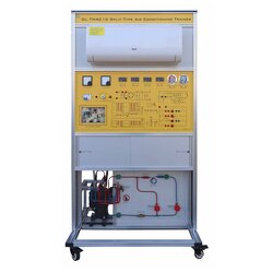
Didactic station for cooling, with split-type air conditioning of 9000 BTU/h, reverse cycle (hot/cold). An air conditioner is basically a cooler without its cabinet and its basic parts are the compressor and the coil. It uses the evaporation of a refrigerant fluid (the gas circulating in the coil) to provide cooling. The mechanisms of the cooling cycle are the same as those in an apartment's fridge and air conditioning. It uses a non-flammable gas compressed by a compressor. Observe the steps of a cooling cycle on an air conditioner: 1. The compressor compresses the cold gas, causing it to heat up at high pressure (shown in red in the diagram above). 2. This hot gas flows through a heat exchanger to dissipate the heat and condense into a liquid state. 3. The liquid flows through an expansion valve and in the process vaporizes to become cold gas at low pressure (shown in blue in the diagram above). 4. This cold gas flows through a heat exchanger which allows the gas to absorb heat and cool the air inside the building. Mixed with the coolant, there is a small amount of low-density oil. This oil lubricates the compressor. DIDACTIC ACTIVITIES 1. Temperature measurements; 2. Pressure measurements; 3. Alternating current measurements; 4. Understanding the Mollier diagram; 5. Understanding thermodynamic tables; 6. Reheat temperature measurements; 7. Observing system performance by differential temperature measurement; 8. Observation of the physical condition of the gas through a liquid inspection glass; 9. Gas collection; 10. Overheating and undercooling control; 11. Simulation of loss of performance in the capacitor by failure insertion; 12. Observation of the effect of the lack of forced ventilation for heat exchange by failure insertion; 13. Observation of the effect of lack of gas compression by failure insertion; 14. Observation of the effect of forced ventilation with inadequate RPM for heat exchange by failure insertion; 15. Observation and understanding of the operation of a reverse cycle. The components of the equipment are part of a real air conditioning system, so they clearly show their complete operation and regulation, allowing the student to identify the main components such as pressure gauges, pressure switches, condensers, evaporators, electrical connection diagnostics and monitoring of the working conditions of the machines, this allows students to be trained in maintenance. In your simulation panel, common mechanical and electrical failures can occur in most air conditioning systems. During operation, the heating and cooling cycles can be regulated, and any physical differences, such as pressure and temperature, can be observed. Electrical faults that can be diagnosed are: • FAULT 1: Solenoid switch in bypass • FAULT 2: The blower relay is switched off • FAULT 3: The compressor relay switches off • FAULT 4: The fan condenser is switched off The insertion of electrical faults causes mechanical failures in the thermo-hydraulic circuit for maintenance and troubleshooting exercises. ower supply: Single-phase, 3-wire.
TECHNICAL DETAILS OF THE SYSTEM Main control panel consisting of: • Power supply: Single-phase, 3-wire. • Two-digit thermometers; • Protection circuit breaker; • On/off switch for power supply; The system consists of a split-type air conditioning 9000 BTU, 220Vac, reverse cycle (cold and heat), installed on an anodized aluminum structure, with wheels, equipped with simulation of 4 electrical faults and front with thermo-hydraulic circuit with screen printing. The system has identified its components and its operation, it also has pressure gauges to measure suction and discharge. It is installed on a bench with wheels and is designed to support its entire structure and components, as well as being robust and easy to carry, its size aids in the visualization and manipulation of the components at the time of the study. The front panel shows the schematic diagram of the air conditioning and cooling system. it offers a range of components and test points and overheat protection that are part of an air conditioning system strategically positioned for simulations and labeled with each item's respective name. TOOL KIT Kit for the study of projects for cutting, folding, welding and expansion of pipes within the system with pressure sensor unit, with four vacuum gauges to monitor the pressure of the air conditioning system and the cooling system, which contains: - 01 current clamp - 01 3x1 1 / 4.5 / 16.3 / 8 manual pipe bending machine. - 01 high accuracy analog vacuum gauge. - 01 tube piercing valve up to 3/8. - 01 burr bit punch. - 01 eccentric flange without ratchet with bench screw in inches. - 01 gas manifold assembly r22 and r410a with 90 cm hoses and two adapters. - 01 tube bending spring set, 1 / 4.3 / 8.1 / 2.5 / 8 and 3/4. - 01 pipe cutter from 1/8 to 1/1/8 - 01 mini tubes cut up to 5/8 for hard-to-reach locations. - 01 leak detector. - 01 extension pin for bag making. - 01 torch up to 1800 degrees welds tubes up to 1 inch. - 01 recharge torch. - 01 non-removable five-tip thermometer, ideal for comparing temperature and overheating and undercooling and air insufflation. - 01 dual stage 5.5 cfm vacuum pump. THE SYSTEM INCLUDES: - Operation Manual - 12-month warranty - Activities Manual
What is this?
These percentage scores are an average of 0 user reviews. To get more into detail, see each review and comments as per below
If you have used this product, support the community by submitting your review


