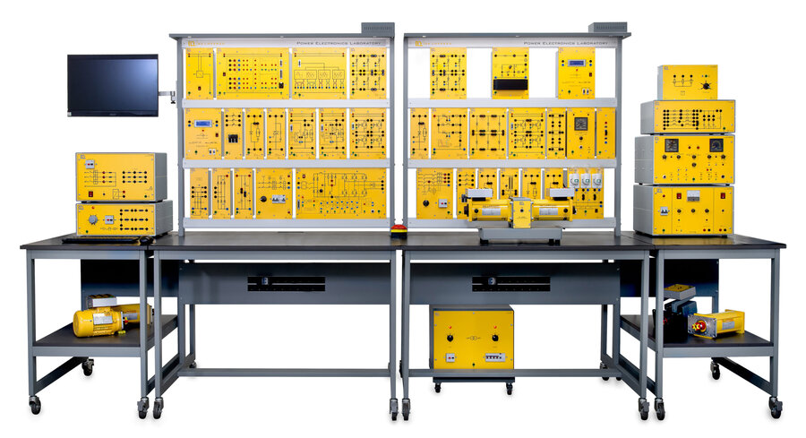
Power Electronics Laboratory (DL PELTOT)
PL-248897
Power Electronics is the branch of Electronics that studies the devices, circuits, systems and procedures for the processing, control, and conversion of electrical energy. Technological development in solid-state electronics and the semiconductor field has transformed power electronics providing active devices with higher switching speeds, and power handling at lower costs. The power electronic devices commonly found in the industry are Diodes, SCR, TRIAC, MOSFET, and IGBT. Their different attributes dictate how they are used in different applications, according to the type of input and output power: AC to DC, AC to AC, DC to DC, or DC to AC. This technology can be found in a wide range of settings impacting everyday life, from consumer electronics, industrial applications, transportation, telecommunications, power systems, to space technology. Power Electronics can be defined as the application of solid-state electronics for the control and conversion of electrical power. The technological development in solid-state electronics and its integration with microcontroller technology has transformed power electronics from a static conversion technology to an essential element embedded in most of our electrical and electronic systems powering most of our every-day applications. The PEL laboratory has been developed as a comprehensive hands-on training solution to study all the main devices and the power conversion techniques commonly used in the industry. It is divided into 5 main sections: AC to DC conversion (Rectifiers), AC to AC conversion (AC voltage controllers), DC to DC conversion (Choppers), DC to AC conversion (Inverters) and electrical drive applications for DC and AC motors. The digital control signals are generated using state of the art FPGA technology. Thanks to its high performance, a single reprogrammable data acquisition and control module gives great flexibility and reliability to reconfigure the laboratory according to the type of converter under study. It provides all the signalling while simultaneously acquiring the experiment data and waveforms. The laboratory is monitored and controlled through an intuitive user interface that gives access to the main parameters of the system. The software will guide the student through the different proposed experiments with clear schematics, wiring diagrams and instructions providing feedback at each step. The morphing interface will adapt to the type of converter under study showing only the parameters that are available for the type of circuit. The different acquired signals can be visualized using a dedicated multichannel virtual oscilloscope, processed using the on-board math functions or exported and stored for further analysis. KEY CHARACTERISTICS
- Modularity
- Reconfigurable lab composed of discrete elements.
- Industrial grade devices.
- FPGA Based control and data acquisition
- The full system is controlled by an FPGA based data acquisition and control module.
- The NI Linux Real‑Time processor combined with isolated I/Os, gives great flexibility and reliability to implement digitally controlled power converters.
- A PC user interface generates the control signals for the converter under study, controls its main parameters, and acquires and processes the characteristic waveforms using the powerful embedded mathematical tools.
- Didactic approach
- All-in-one solution that gives the student a full view of power electronics.
- Gradual course that starts from the study of the power semiconductors and the main convertion strategies, to the study of their application as power supplies and drives.
- Hands-on, experiment-based, training platform.
- Skills development
- Students interact with real industrial equipment.
- Study and implementation of the different power conversion techniques used in the industry.
- Study of main power electronics applications and electrical drives.
- The main controller SW is programmed using LabVIEW, a language widely used in the industry and academy.
- Development of analytical and troubleshooting skills through practical hands-on training.
- - Quality and Safety
- Made and designed in Italy using all the quality and safety standards following the CE directives for power devices:
- CEI - EN 61010-1
- CEI - EN 61439-1
- CEI - EN 60335-1
- No need for shunt resistors or current probes
- No need for differential high voltage probes
- No need for isolated power supply required by the oscilloscope
- No restriction of common ground shared by channels
The DEL PELTOT trainer has been designed to provide students with a fully comprehensive knowledge in power electronics systems, in a compact and flexible solution.
Modules List DL PELTOT
- DL 2106T01: Control module,
- DL 2106T02: SCR and TRIAC driver,
- DL 2106T03: Single MOSFET with driver,
- DL 2106T04: Single IGBT with driver,
- DL 2106T05: IGBT H-bridge with driver,
- DL 2106T06: Frequency converter,
- DL 2106T11: Silicon diode,
- DL 2106T12: Diode stack,
- DL 2106T13: Three-phase diode bridge,
- DL 2106T14: SCR,
- DL 2106T15: SCR stack,
- DL 2106T16: SCR with turn-off circuit,
- DL 2106T17: TRIAC,
- DL 2106T18: Light dimmer - fault simulator,
- DL 2106T21: Fuse box,
- DL 2106T22: EMI filter,
- DL 2106T23: Capacitors,
- DL 2106T24: Switching transformer,
- DL 2106T25: 1,omega, shunts,
- DL 2106PS: DC power supply,
- DL 2106SPS: Single-phase power supply,
- DL 2106TPS: Three-phase power supply,
- DL 2106RLC:R-L-C load,
- DL 2109D33: True RMS meter ,
- DL 4236: Load manager,
- DL 2655: Variable 3-phase transformer,
- DL 12B12: Battery,
- DL 2025DT: Tachometer,
- DL 10200A1: Shunt motor,
- DL 10250A1: Shunt Excited DC Generator ,
- DL 10120A1: Slip-ring 3-phase motor,
- DL 10120RA: Rotor rheostat,
- DL 2108T26-LP: Brushless controller,
- DL 2108T26BR: Brake resistor,
- MOTBRA1.3NM: 1.3Nm brushless motor,
- DL 10400: Base For Machines Coupling ,
- DL 10115A1: Squirrel cage motor,
- DL 2600TTI: Isolated transformer,
- DL T12090_SK: 120x90 working bench,
- DL T06090: 60x90 working bench,
- DL A120-3M:Frame with 3 levels, basic version ,
- DL SP-A120-LED: Upper base with LED strip, for DL A120-3M,
- DL PCGRID: Computer All in one,
- TLDCA2.0: Kit of connecting leads,
- DL 1196: Holder for leads.
The laboratory is subdivided into 5 major study areas:
- AC-DC Conversion
- AC-AC Conversion
- DC-DC Conversion
- DC-AC Conversione
- Motor drivers
DL PEL201:AC-DC CONVERSION
The DL PEL201 is a multipurpose bench to study the conversion from alternating current to direct current, using different configurations of non-controlled and controlled rectifiers, to later apply these concepts to drive AC and DC motor drives. The course is divided in two parts: the study of uncontrolled rectifiers using silicon diodes and the study of controlled rectifiers using Silicon Controlled Rectifiers (SCR). Its modular structure makes it easy to reconfigure the system to perform several experiments in various subjects such as uncontrolled diodes and static converter circuits, thyristors, single pulse/two-pulse midpoint converters, to name a few.
DIODES AND UNCONTROLLED RECTIFIERS
- Silicon diode
- Uncontrolled single-phase half-wave rectifier
- Uncontrolled single-phase centre-tapped full-wave rectifier
- Uncontrolled single-phase bridge rectifier
- Uncontrolled three-phase half-wave rectifier
- Uncontrolled three-phase centre-tapped full-wave rectifier
- Uncontrolled three-phase bridge rectifier
SCR AND CONTROLLED RECTIFIERS
- SCR
- Controlled single-phase half-wave rectifier
- Controlled single-phase centre-tapped full-wave rectifier
- Half controlled single-phase bridge rectifiers
- Fully controlled single-phase bridge rectifier
- Controlled three-phase half-wave rectifier
- Controlled three-phase centre-tapped full-wave rectifier
- Dual 3-ph centre-tapped half-wave rectifier
- Half controlled three-phase bridge rectifier
- Fully controlled three-phase bridge rectifier
DL PEL202: AC-AC CONVERSION
The DL PEL202 is a multipurpose bench to study the conversion from alternating current to alternating current. Its main fields of applications are in the control of temperature, lighting, and induction motors (with phase-control, on-off control and proportional time control). The course is divided into two sections: the first part studies thyristors and controlled AC/AC converters using power components as diodes, SCR and Triacs with two and six pulse control units and the second part shows a standard application with the study of a double-time constant light dimmer circuit consisting of Triac and Diac with fault simulation. Its modular structure makes it easy to reconfigure the system to perform several experiments in various subjects such as Triac, single-phase and three-phase controllers, to name a few.
THYRISTORS AND AC VOLTAGE CONTROLLER
- TRIAC
- Fully controlled single-phase AC voltage controllers
- Fully controlled single-phase AC voltage controllers with TRIAC
- Half controlled single-phase AC voltage controllers
- Fully controlled 3-ph AC voltage controller
- Half controlled 3-ph AC voltage controller
- Two-phase controlled 3-ph AC voltage controller
LIGHT DIMMER FAULT SIMULATOR
- Phase control for the regulation of lighting with fault simulation.
- Double time-constant standard light dimmer circuit consisting of triac, diac, two control potentiometers, resistors and capacitors.
- 20 faults can be switched on using switches located behind a cover. Typical faults: interruptions, short-circuit, faulty components and faulty design.
DL PEL203: DC-DC CONVERSION
The DL PEL203 is a multipurpose bench to study the conversion from direct current to direct current, and its main fields of applications such as DC power supplies and DC motor drives. The course is divided into two sections. The first part covers choppers and studies the conversion from fixed DC input to a variable DC output directly with the use of SCR, MOSFET and IGBT. The second section studies switching mode power supplies and analyzes the properties of the PWM control with the use of circuits as flyback and forward converters. Its modular structure makes it easy to reconfigure the system to perform several experiments in various subjects such as step-up/step-down converters, speed control of a DC motor, asymmetric half-bridge forward converter, to name a few.
CHOPPERS
- Switching devices (SCR with turn-off circuit, MOSFET, IGBT)
- Buck converter with SCR with turn-off circuit, PWM
- Buck converter with IGBT, PWM
- Buck converter with MOSFET, PWM
- Buck converter with MOSFET, PFM
- Buck converter with MOSFET, TPC
- Boost converter with IGBT, PWM
- Boost converter with IGBT, TPC
- Inverting converter with IGBT, PWM
ISOLATED SWITCHING MODE POWER SUPPLY
- Flyback converter with IGBT, PWM
- Forward converter with IGBT, PWM
- Asymmetric half-bridge forward converter with IGBT, PWM
DL PEL204: DC-AC CONVERSION
The DL PEL204 is a multipurpose bench to study the conversion from direct current to alternating current, and its main fields of applications such as AC motor drives and AC uninterruptable power supplies. The trainer is designed to study the properties of the inverter with a Pulse Width Modulation control. Its modular structure makes it easy to reconfigure the system to perform several experiments in various subjects such as four-quadrant drive with cycloconverter, control of stator voltage with three-phase AC voltage controller, variable-frequency drive with space vector PWM (SVPWM), to name a few.
INVERTERS
Fundamentals of inverter
- 1-ph half-bridge inverter
- 1-ph bridge DC chopper, PWM
Single-phase inverter
Three-phase inverter
Multi-level inverter
DL PEL205: MOTOR DRIVES
The DL PEL205 is a multipurpose bench for AC and DC motor drives where power electronics converters are studied as interfaces between input power and motors to control speed and position. The trainer is dedicated to the study of different types of machine drives: the DC motor drives with inner current loop, the AC slip-ring motor drives with rotor resistance regulation, and AC squirrel cage motor based variable frequency drives, all of them with speed control. In order to simulate various loading conditions for both DC and AC motors, we have introduced a brushless motor servo drive system that operates in both speed and torque control modes, supporting bidirectional rotation of brushless motors to facilitate four-quadrant operation for DC motors. Additionally, it features display capabilities, protection mechanisms, and supports speed and torque feedback, enhancing its user-friendliness and closed-loop feasibility. Its modular structure makes it easy to reconfigure the system to perform several experiments in various subjects such as single-phase full-bridge DC chopper/inverter (square wave or sine wave with PWM control), frequency converter, to name a few.
DC MOTOR DRIVE
DC motor drive by single-phase rectifiers
DC motor drive by three-phase rectifiers
CONSTANT FREQUENCY DRIVE – SLIP RING MOTOR
Stator voltage control
Rotor resistance control
VARIABLE FREQUENCY DRIVE – SQUIRREL CAGE MOTOR
Frequency converter
Squirrel cage motor
- 1-ph bridge inverter, 180° conduction
- 1-ph bridge inverter, sinusoidal PWM
- 1-ph bridge inverter, square-wave PWM
- 3-ph bridge inverter, 180° conduction
- 3-ph bridge inverter, sinusoidal PWM
- 1-ph neutral point clamped (NPC) 5-level inverter, unchopped
- 1-ph neutral point clamped (NPC) 5-level inverter, PWM
- Single-quadrant drive with 1-ph controlled rectifier
- Single-quadrant drive with 1-ph controlled rectifier for closed loop armature voltage control
- Single-quadrant drive with 1-ph controlled rectifier for closed loop armature voltage control with feedforward
- Single-quadrant drive with 1-ph controlled rectifier for single closed loop speed control
- Single-quadrant drive with 1-ph controlled rectifier for dual closed loop speed control
- Two-quadrant drive (I-IV) with 1-ph controlled rectifier
- Two-quadrant drive (I-III) with 1-ph controlled rectifier
- Two-quadrant drive (I-III) with 1-ph controlled rectifier for dual closed loop speed control
- Four-quadrant drive with 1-ph controlled rectifier
- Four-quadrant drive with 1-ph controlled rectifier for dual closed loop speed control
- Single-quadrant drive with 3-ph controlled rectifier
- Single-quadrant drive with 3-ph controlled rectifier for dual closed loop speed control
- Stator voltage control with variac
- Stator voltage control with AC voltage controller
- Speed control by stator voltage control with AC voltage controller
- Rotor resistance control with rheostat
- Rotor resistance control with pulsed resistor
- Speed control by rotor resistance control with pulsed resistor
- Rotor resistance control with Scherbius static drive
- Speed control by rotor resistance control with Scherbius static drive
- Operation of the frequency converter
- Input controlled rectifier
- Output inverter
- DC link brake chopper
- Preliminary investigation of the squirrel cage motor
-
Modulation methods of frequency converter
- Six-step modulation
- Square wave PWM
- Trapezoidal wave PWM
- Sinusoidal wave PWM (SPWM)
- Space vector PWM (SVPWM)
- 3rd harmonic injection
Induction motor control following U/f characteristic
- Motor magnetization for linear U/f characteristic
- Extra start magnetization
- IxR compensation
- Operation in standard converter setting
- Scaled-down operation in star connection
Speed control
- Slip compensation
- Closed loop speed control
What is this?
These percentage scores are an average of 0 user reviews. To get more into detail, see each review and comments as per below
If you have used this product, support the community by submitting your review


