Satellite Communication Network Technology Trainer (DL 2598SC)
PL-420281
This trainer is mainly designed for "Satellite Communications", "Mobile Communications Engineering", "Microwave Technology and Antennas", "Microwave Electronics" and other topics in microwave and satellite communications, electronic information engineering, military communication network and command in major technical secondary schools, including the latest products developed for graduation projects. The satellite communication is a method that uses electromagnetic waves in space as a carrier to transmit information. It is not subject to geophysical interference. Therefore, satellite communication is one of the other wireless communication methods in aerospace communications, navigation, and personal remote area communications, especially in military communications. This equipment adopts a fully open microstrip circuit design concept, allowing students to more intuitively understand and master the design methods of microstrip active and passive circuits, and can directly train students’ hands-on, thinking, and innovation abilities. It lays a practical foundation for future practical work, and it can also be used for scientific research experiments, e.g. to do simulated self-loop communication experiments.
According to the different orbits of communication satellites above the earth, they can be divided into synchronous and non-synchronous satellite communication systems. This equipment is a geosynchronous satellite communication system. In addition, there are several frequency band allocations for satellite communications. Among them are L-band, C-band, Ku-band, and Ka-band. This equipment uses the C-band, which is the earliest and most widely used.
It has the following features in C-band:
- 5.925 ÷ 6.425GHz for transmission,
- 3.7 ÷ 4.2GHz for reception,
- 500MHz for sending bandwidth,
- 500MHz for receiving bandwidth.
It adopts a modular structure, and all microwave circuits are open and visible to facilitate students' intuitive learning. It is designed and manufactured according to the secondary frequency conversion scheme common to industrial products, to facilitate the students to integrate with reality. It can be flexibly combined to be configured for simplex or duplex communication and, depending on the terminal equipment, Frequency Division Multiple Access (FDMA), Time Division Multiple Access (TDMA), Code Division Multiple Access (CDMA), or Hybrid Multiple Access (HMA) can be used. The experimental box in this equipment takes FDMA as an example.
PERFORMANCE PARAMETERS
Main performance indicators of sending equipment
- Transmission frequency: 5.925 ÷ 6.425GHz,
- Emission level: 0dBm ÷ 10dBm (1 ÷ 10mW), 1dB step,
- System gain: ≥ 50dB,
- First IF (low IF): 140MHz,
- Second IF (High-mid frequency): 1.06GHz,
- Bandwidth (per band): 20 ÷ 40Mhz,
- Video and Audio modulation methods: QAM,
- Modular output level: -5dBm ± 2dB.
Main performance indicators of receiving equipment
- Working frequency: 3.7 ÷ 4.2GHz,
- Receiver sensitivity: -80 ÷ -50dBm,
- System gain: ≥ 60dB,
- First IF (low IF): 140MHz,
- Second IF (High-mid frequency): 1.165GHz,
- Gain control range (MGC, AGC): ≥ 31.5dB,
- Video and Audio demodulation methods: QAM.
Local oscillator frequency combiner
- L band frequency range,
- Receive: 1235 ÷ 1305MHz,
- Send: 920 ÷ 990MHz,
- Step: 1MHz.
- C-band frequency range,
- 4.8 ÷ 5.5GHz,
- Step: 20MHz.
- Frequency stability: ± 5ppm or (1 ÷ 2) x 10-5,
- Local oscillator combiner phase noise: -80dBc/Hz@10k, -90dBc/Hz@100k (typical value),
- Spurious output: 50dBc (typical value).
Analog satellite transponder
- Uplink receiving frequency range: 5.925 ÷ 6.425GHz,
- Downlink transmission frequency range: 3.7 ÷ 4.2GHz,
- Communication satellite transponder local oscillator frequency: 2 ÷ 2.25GHz,
- System gain: 40 ÷ 70dB,
- Receive sensitivity: -70 ÷ -30dBm,
- Frequency stability: ± 5ppm or (1 ÷ 2) x 10-5,
- Phase noise: -80dBc/Hz@10k, -90dBc/Hz@100k (typical value).
EXPERIMENTAL FUNCTIONS
- Can transmit colour image signals and voice signals at the same time,
- Frequency shift repeater for mobile communications,
- Microwave components and microwave circuit system testing,
- Microwave Antenna Test Experiment,
- Can provide practical microwave circuit design models (including amplifiers, various filters, mixers, and power dividers among others).
EXPERIMENTAL CONTENT
Overview of satellite communications
- Main features of satellite communications,
- Composition of satellite communication network,
- FDMA in satellite communication.
System principles, features, and functional technical indicators
- Main technical indicators and functions of the transceiver system,
- Experimental system principal composition,
- Experimental system characteristics.
Satellite communication and networking experiment
- Peer-to-peer communication,
- Network duplex communication (optional),
- Connection between satellite communication network, microwave communication and mobile communication network (optional),
- Satellite broadcasting network (optional).
Extended experiments in the experimental box
- Experiments for additional circuits in the experimental box,
- Microwave antenna test experiment.
Microwave and satellite communication system components and unit circuit testing experiments
- IF Image Modulator Experiment,
- IF Image Demodulator Experiment,
- Experiments on IF amplifier, bandpass filter, and gain control functions,
- Bandpass, bandstop filters and amplifier experiments for high and medium frequency division systems,
- Frequency synthesizer experiment,
- Experiments on C-band up and down-conversion systems,
- Test experiment of C-band receiving system,
- Test experiment of C-band transmitting system,
- Test experiment of C-band communication satellite transponder.
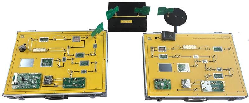
CONFIGURATION LIST
- Satellite communication network technology training platform (uplink)/1 set,
- Satellite communication network technology training platform (downstream)/1 set,
- Satellite transponder/1 set,
- 4G antenna/1 pair,
- 6G antenna/1 pair,
- Power cables and auxiliary cables.
- Detailed theoretical and practical manual.
- For real time spectrum analysis:
- Frequency range: 5kHz ÷ 8GHz,
- Real time analysis bandwidth: ≥ 40MHz,
- Maximum sampling rate: 51.2MHz,
- Display mode: density spectrum, waterfall plot, power vs. time,
- Trigger modes: External Trigger, Intermediate Frequency Power, PPS Second Pulse, Gate Control Scan, Frequency Template.
- For scanning frequency spectrum analysis:
- Resolution bandwidth: 1Hz ÷ 5MHz,
- Noise level: -165dBm,
- Scanning time: 20μs ÷ 3000s (non-zero scanning width), 5ms ÷ 3000s (zero scanning width),
- Comprehensive amplitude accuracy: ± 1.5dB.
- For vector network analysis:
- Frequency range: 100kHz ÷ 8GHz,
- Measurement parameters: S11, S21,
- RF output power: 0dBm, 30dB adjustable,
- Display modes: echo/Standing Wave Ratio (SWR), insertion loss, Smith chart, phase, group delay,
- Effective directionality: ≥ 38dB (1MHz ÷ 8GHz),
- Dynamic range: 80dB (S21, 10kHz RBW, Log mag, Average = 50, >10MHz).
Power supply: single-phase from the mains.
SUGGESTED NECESSARY INSTRUMENT (NOT INCLUDED)
A spectrum analyzer with functions such as real-time spectrum, scanned spectrum, vector network analysis, antenna feeder measurement, field strength measurement, interference positioning, power measurement, signal modulation analysis, etc.
What is this?
These percentage scores are an average of 0 user reviews. To get more into detail, see each review and comments as per below
If you have used this product, support the community by submitting your review


