Manual Reactive Power Compensation Application (AEL-MRPC)
PL-844450
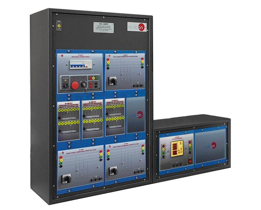
The Manual Reactive Power Compensation Application, “AEL-MRPC”, developed by EDIBON, is designed to analyze the impact of reactive power consumption in AC electrical systems and to explore the techniques used to improve energy efficiency through power factor correction.
In many industrial electrical applications, the presence of reactive power is necessary for the proper functioning of the circuit. While active (real) power supplies the energy needed to perform useful work —such as running motors, lighting, or heating— reactive power plays a critical role in regulating voltage and ensuring efficient power transfer through the grid and distribution lines.
The power factor (PF) is defined as the ratio of active power (in watts) to apparent power (in volt-amperes), and it reflects how effectively electrical power is utilized. A power factor closer to 1 indicates higher efficiency. Since apparent power combines both active and reactive components, reducing reactive power brings the power factor closer to 1 without affecting the real power —thereby enhancing the overall efficiency of the system.
However, despite its drawbacks, reactive power is essential to maintain voltage levels across the electrical network. Insufficient reactive power leads to voltage instability and hinders the delivery of active power, while an excess of reactive power can result in overheating, unwanted voltage drops, and energy losses along transmission lines.
In practical scenarios, most electrical loads are inductive in nature, and thus they require reactive power to operate. Installing capacitors or capacitor banks in parallel with the load provides local reactive power, reducing the amount that must travel through the distribution network. This also minimizes the phase angle between voltage and current, improving the power factor.
The “AEL-MRPC” application incorporates different types of switchable loads (resistive, inductive, and capacitive) to facilitate comprehensive study of power factor correction techniques.
In addition, the system includes a network analyzer for real-time measurement of key electrical parameters such as current, voltage, frequency, power, and power factor. These measurements are essential for accurate evaluation and implementation of reactive power compensation strategies.
- AEL-MRPC. Application: :
The “AEL-MRPC” application includes the following elements:
N-ALI01. Industrial Main Power Supply Module.
- Supply voltage: 400 VAC, 3PH + N.
- ON / OFF removable key.
- Output voltage connections:
- Three-phase + Neutral: 400 VAC.
- Single-phase: 230 VAC.
- Three-phase supply hose with IP44 3PN+E 32 A 400 V connecting plug.
- Differential magnetothermal 4 poles, 25 A, 30 mA AC 6 KA.
- Emergency stop push-button.
N-REFT. Three-phase Commutable Resistor Load Module.
- Nominal voltage: 400 VAC.
- Resistance: 3 x 150 Ohm.
- Nominal current: 1.6 A.
- Manual switch to turn ON / OFF resistors.
- Fuses: 3 x 2 A.
- Terminals:
- Four input terminals (3PH + N).
- Four output terminals (3PH + N).
N-CAR18/C. Capacitors for Equivalent Circuit of an Electric Line Module.
- Nominal voltage: 230 VAC.
- Capacitors: 2 x (7 x 1 µF).
N-INDT. Three-phase Commutable Inductive Load Module.
- Nominal voltage: 400 VAC.
- Inductance: 1.4 H.
- Nominal current: 1.6 A.
- Manual switch to turn ON / OFF inductances.
- Fuses: 3 x 2 A.
- Terminals:
- Four input terminals (3PH + N).
- Four output terminals (3PH + N).
N-MED60. Network Analyzer Module.
- ON / OFF switch.
- Supply voltage: 230 VAC.
- Fuses: 3 x 10 A.
- Input terminals: three-phase input connection with neutral to the measurement point.
- Output terminals: three-phase output connection with neutral to the measurement point.
- Network analyzer display. It shows:
- Active, reactive and apparent power.
- Active, reactive and apparent energies.
- Lines and phase currents:
- IL-N: 0.03 to 10 A.
- IL-L: 0.09 to 10 A.
- Line and phase voltages:
- VL-N: 160 V to 480 V.
- VL-L: 277 V to 830 V.
- Frequencies: 65 to 458 Hz ± 0.1 Hz.
- Power factor for resistive, inductive and capacitive loads.
- Cables and Accessories, for normal operation.
- This unit is supplied with the following manuals: Required services, Assembly and Installation, Starting-up, Safety, Maintenance and Practices manuals.
EXERCISES AND PRACTICAL POSSIBILITIES TO BE DONE WITH THE MAIN ITEMS
- Wiring of resistive, inductive and capacitive loads.
- Measurement of the apparent, active and reactive powers consumed by a receiver in a pure resistive circuit.
- Measurement of the apparent, active and reactive powers consumed by a receiver in a pure inductive circuit.
- Measurement of the apparent, active and reactive powers consumed by a receiver in a pure capacitive circuit.
- Measurement of the apparent, active and reactive powers consumed by a receiver in a RL circuit.
- Measurement of the power factor of a receiver in a RL circuit.
- Calculation and wiring of the capacitive load needed to carry out an adequate power factor compensation.
- Comparison of apparent, active and reactive power after power factor compensation.
- Measurement of power factor after the compensation.
- Several other exercises can be done and designed by the user.
What is this?
These percentage scores are an average of 0 user reviews. To get more into detail, see each review and comments as per below
If you have used this product, support the community by submitting your review


