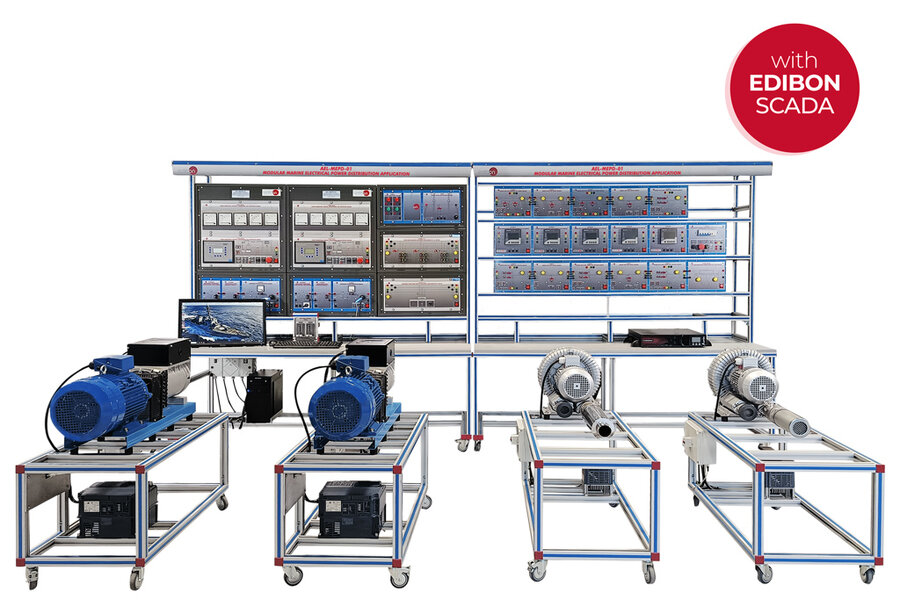
Modular Marine Electrical Power Distribution Application, with SCADA (AEL-MEPD-01)
PL-178830
The Modular Marine Electrical Power Distribution Application, “AEL-MEPD-01”, has been specifically designed by EDIBON to offer complete theoretical and practical training in marine power generation and electrical distribution systems. This training system addresses essential topics such as marine switchboard configuration, onboard power generation, propulsion control, uninterruptible power supplies (UPS), critical and non-critical circuits, and generator synchronization—either within an isolated marine grid or while connected to shore power.
The onboard power generation system features two motor-generator sets, each with independent control, monitoring, and protection modules to safeguard against various electrical faults. These generators support both voltage and frequency regulation or power output adjustment, depending on the selected operational mode. The system operates in either grid-forming or grid-following mode, with automatic mode selection based on the status of all circuit breakers.
The marine switchboard distribution setup includes multiple circuit breakers arranged in a ring-type configuration with two main busbars and three interconnection branches. To avoid incorrect synchronization, the breakers have safety locking mechanisms that activate when voltage is detected at their terminals. Additionally, four synchronization switches manage the connection of different power sources by comparing phase angles before engagement.
The propulsion system, connected to the main electrical bus, consists of two propeller systems powered by variable frequency drives. Using the integrated SCADA software, students can simulate and analyze real-world parameters involved in marine propulsion for mid-sized vessels, such as ship speed, thrust, torque, advance coefficient (based on the Wageningen series), and total resistance forces.
A critical feature of the “AEL-MEPD-01” is the simulation of blackout recovery. If both main power generators fail, the integrated UPS system enables the study of emergency power recovery procedures and ensures continuity of vital onboard services and loads.
The “AEL-MEPD-01” includes a full-featured SCADA Control and Data Acquisition System to supervise and operate the complete electrical system. It accurately replicates a full shipboard power infrastructure, including the Navigation Bridge, onboard power generation units, distribution switchboard, propulsion controls, and ship load management panels. To simulate dynamic onboard energy usage, students can draw a power consumption curve in real-time by varying active load parameters.
- AEL-MEPD-01. Application:
N-ALI12. Power Supply Module with Phase Sensor 3PH+N/400 VAC.
- Supply voltage: 400 VAC, 3PH + N.
- ON / OFF removable key.
- Verification of phase sequence.
- Output voltage connections:
- Three-Phase + Neutral: 400 VAC and Single-Phase: 230 VAC.
- Single-Phase: 230 VAC.
- Three-Phase supply hose with IP44 3PN+E 32 A 400 V connecting plug.
- Differential magnetothermal 4 poles, 25 A, 30 mA AC 6 KA.
- Emergency stop push button.
N-BUS10. Busbar with Two Switches and Feeder Module.
- Nominal voltage: 230 VAC.
- Two busbar connection terminals.
- Three feeder terminals.
- Five indicator lamps:
- Status lamp.
- Blocked KM1 lamp.
- Blocked KM2 lamp.
- KM1 state indicator lamp.
- KM2 state indicator lamp.
- Four push buttons:
- Open KM1 push button.
- Close KM1 push button.
- Open KM2 push button.
- Close KM2 push button.
- Voltage detector lamp: Nominal voltage: 400 VAC.
- Two circuit breakers.
N-BUS11. Busbar with Link Switch Module.
- Nominal voltage: 230 VAC.
- Two busbar connection terminals.
- One switch to enable synchronization.
- Four indicator lamps:
- Status lamp.
- Blocked KM1 lamp.
- Checking phases lamp.
- KM1 state indicator lamp.
- Two push buttons:
- Open KM1 push button.
- Close KM1 push button.
- Two voltage detector lamps: Nominal voltage: 400 VAC.
- Circuit breaker.
- Two auxiliary contacts:
- Normally open contact.
- Normally closed contact
N-BUS12. Busbar with Dual Feeder and Switches Module.
- Nominal voltage: 230 VAC.
- Two busbar connection terminals.
- Two feeder terminals.
- Five indicator lamps:
- Status lamp.
- Blocked KM1 lamp.
- Blocked KM2 lamp.
- KM1 state indicator lamp.
- KM2 state indicator lamp.
- Four push buttons:
- Open KM1 push button.
- Close KM1 push button.
- Open KM2 push button.
- Close KM2 push button.
- Voltage detector lamp: Nominal voltage: 400 VAC.
- Two circuit breakers.
N-EALD/M. Power Network Analyzer with Modbus TCP/IP Module.
- The network analyzer module allows fulfilling measurements, displaying and analyzing all the parameters of the AC electrical networks. It has an LCD screen and push-buttons for the navigation through the different menus. It includes specific software for monitoring current and voltage curves, harmonics display, tariffs programming, alarms programming and electrical parameters storage.
- Features:
- Multifunctional three-phase power meter:
- Three-phase and single-phase voltage. Up to 690 VAC L-L.
- Line and neutral nominal current: 10 A.
- Active, reactive and apparent power.
- Suitable frequencies: 25 Hz, 50 Hz, 60 Hz and 400 Hz.
- Display of the V-I vector diagram.
- Supply voltage: 85 – 265 VAC.
- Energy quality control:
- Current and voltage individual harmonics measurement. Up to the 40th harmonic.
- Voltage and current THD, TDD and K-Factor.
- Maximums and minimums display.
- Waveforms display, 128 samples/sec.
- Events and data storage:
- Harmonics analyzer: Voltage and current THD, current TDD and K-Factor, up to the 40th harmonic. Current and voltage harmonic spectrum and angles.
- Tariff programming:
- Class 0.5S IEC 62053 – 22, active and reactive power in four quadrants.
- Measurement of the total and per phase three-phase active, reactive and apparent powers.
- Usage time, four energy/demand records of total tariffs.
- Eight tariffs, four seasons and four types of days.
- Automatic daily report of energy consumption maximums and minimums.
- Communications: MODBUS TCP/IP communication.
N-ERP-PGC03. Power Generation, Control, Measurement, and Protection Module
- Three-phase wattmeter: Measured range: 0 – 1.5 kW.
- Three-phase varmeter: Measured range: 0 – 1.5 KVAr.
- Voltmeter: Measured range: 0 – 500 V.
- Frequency meter: Measured range: 45 – 55 Hz.
- DC meter: Measured range: 0 – 10 A.
- Generator protection relay module.
- Single-phase supply voltage: 230 VAC.
- “Island grid/parallel grid” control switch.
- “Local/remote” control switch.
- Manual control switches of the relay:
- SW1, emergency stop.
- SW2, automatic start of the generator-motor group.
- SW3, protections reset pushbutton.
- SW4, generator frequency control activation.
- SW5, 52 G1 synchronization circuit breaker closure manual permission.
- State light indicators.
- Alarm light indicators.
- Synchronization safety key.
- Emergency stop pushbutton.
- ON / OFF switch.
- Connection terminals.
- The “N-ERP-PGC-03” Turbine Protection and Control Module:
- Enables to connect up to 16 generators in parallel-island with distribution of active and reactive load and start/stop operation control in function of the load demand.
- Enables to connect one generator in parallel with the grid.
- Enables different switches control modes, such as opening, closing and synchronization.
- Includes analogical outputs to control voltage and frequency regulators available in the market.
- Three-phase measurement of the grid and generator voltage.
- Three-phase measurement of the generator current and power.
- Single-phase measurement of the grid current.
- Protections:
- Generator protections: max/min. voltage (59/27), max/min. frequency (81O/U), voltage asymmetry, dead bus detection, overload (32), unbalance load (46/F), reverse power/reduce (32R/F), overcurrent time define curve (50/51), inverse time overcurrent (IEC255), fault ground (50N/51N), phases, breakers fault.
- Motor: over/sub speed (12).
- Mains: max/min. voltage (59/27), max/min. frequency (81O/U), vector surge.
GEC-KIT-1. Generator Excitation Circuit Kit 1.
N-AVR/P. Automatic Voltage Regulator Module.
- Input voltage: 0 – 100 VDC.
- Input for voltage regulation signal through PWM control.
- Terminals for PWM signals monitoring.
- Output voltage: 0 – 100 VDC.
- DC ammeter for output current measurement, 0 – 4 A.
- 3-pin female connector for connection to the excitation input of a generator.
- Fuse 5 A
N-TRANS04. Single-Phase Transformer Module 230 VAC/2x35 VAC, 300 VA.
- 230 VAC single-phase input terminals.
- 70 VAC single-phase output terminals.
- 35 VAC single-phase output terminals for two outputs.
- Two-position switch: 0 (open)/1 (closed).
- Fuses:
- Primary side: 2 A.
- Secondary side: 5 A.
N-SPAD01. Single-Phase AC/DC Converter Module 1.
- 0 – 230 VAC single-phase input terminals.
- AC/DC rectifier.
- DC output terminals.
- Filter capacitor for voltage ripple reduction.
- Bypass terminals for filter capacitor connection.
- Fuse 5 A.
GMG4.5K3PH. 4.5 kW Generator-Motor Group.
- Motor-generator group coupled in an aluminum frame with wheels.
- Generator nominal power: 4.5 kVA.
- Generator nominal speed: 3000 rpm.
- Generator nominal output current: 6.5 A.
- Generator nominal excitation current: 4 A.
- Generator power factor: 0.8.
- Generator nominal output voltage: 3 x 400 VAC.
- Frequency: 50/60 Hz.
- Motor nominal power: 5 kVA.
- Motor nominal current: 7.2 A.
- Motor nominal speed: 3000 rpm.
N-REFT-E/1K. Adjustable Three-Phase Resistive Electronic Load Module of 0-1000 W.
- Power consumed: 0 – 1000 W.
- Six 10 A fuses.
- One circuit breaker:
- Nominal voltage: 230 VAC.
- Nominal current: 9 A.
- One resistor: 330 ohms.
- Two yellow voltage detectors: Nominal voltage: 400 VAC
N-INDT-E/1K. Three-Phase Inductive Electronic Load Module of 3X300 Var.
- Power consumed: Three inductance banks of 300 Var each one.
- Six 10 A fuses.
- Three circuit breakers:
- Nominal voltage: 230 VAC.
- Nominal current: 9 A.
- Three inductance banks: 3 x 5 H inductances.
- Two yellow voltage detectors: Nominal voltage: 400 VAC.
N-REF-E/300W. Single-Phase 300W Resistive Electronic Load Module.
- Line terminal of the resistor.
- Circuit breaker with its lamp indicator.
- 150 Ohms and 300 W resistor.
- Neutral terminal of the resistor.
- Selector:
- Position OFF: circuit opened.
- Position ON: circuit closed.
- Two 2 A fuses and one 5 A fuses.
- Over temperature indicator.
- Status indicator.
N-SEL04. Four Light Indicator Module.
- Two red lamps: Input voltage: 2 terminals for each lamp of 230 VAC.
- Two green lamps: Input voltage: 2 terminals for each lamp of 230 VAC.
N-UPS-1PH/2K. 1PH Uninterruptible Power Supply of 2 kVA Module.
- Nominal voltage: 230 VAC.
- 2 voltage detector lams.
- Nominal voltage: 230 VAC.
- UPS:
- Nominal voltage: 208 / 220 / 230 / 240 V.
- Nominal frequency: 50 / 60Hz (auto-detection).
- Frequency range: ± 5 Hz.
- Total Harmonic Distortion (THDv):2% linear load / 5% non-linear load.
- Waveform (battery mode): Pure sinusoidal.
SHPR/2K. Set for Ship Propulsion of 2.2 kW.
- Frequency drive:
- Input voltage: Three phase 400 VAC.
- Rated power: 3 kW.
- Blower pump:
- Nominal power: 2200 W.
- Nominal voltage: 380 VAC.
- Maximum air pressure: 36 kpa.
- Maximum suction pressure: 33 m³/h.
- Noise: 70 dB.
- Conduct diameter: 60 mm.
- Weight: 36 Kg.
- Engineguard: Protection range: 2.4 A – 4 A.
AEL-PC. Touch Screen and Computer
- Touch screen:
- Energy efficiency class: A.
- Screen diagonal: 68.6 cm (27 inch (s)).
- Power consumption (operating): 26 watts.
- Annual energy consumption: 38 kWh.
- Power consumption (standby/off): 0.49 watts.
- Screen resolution: 1920 x 1080 pixels.
- Computer:
- Processor number: Intel Core i7-6600U Processor (4M Cache, up to 3.40 GHz).
- Cache: 4 MB Intel Smart Cache.
- Clock speed: 2.6 GHz.
- # Of cores/# of threads: 2/4.
- Max. TDP/Power: 15 W.
- Memory types: DDR4-2133, LPDDDR3-1866, DDR3L-1600.
- Graphics: Intel HD graphics 530.
- Slot for PCI Express.
The complete unit includes as well:
- Advanced Real-Time SCADA.
- Open Control + Multicontrol + Real-Time Control.
- Specialized EDIBON Control Software based on LabVIEW.
- National Instruments Data Acquisition board.
- Calibration exercises, which are included, teach the user how to calibrate a sensor and the importance of checking the accuracy of the sensors before taking measurements.
- Projector and/or electronic whiteboard compatibility allows the unit to be explained and demonstrated to an entire class at one time.
- Capable of doing applied research, real industrial simulation, training courses, etc.
- Remote operation and control by the user and remote control for EDIBON technical support, are always included.
- Totally safe, utilizing 4 safety systems (Mechanical, Electrical, Electronic and Software).
- Designed and manufactured under several quality standards.
- Optional ICAI software to create, edit and carry out practical exercises, tests, exams, calculations, etc. Apart from monitoring user’s knowledge and progress reached.
- This unit has been designed for future expansion and integration. A common expansion is the EDIBON Scada-Net (ESN) System which enables multiple students to simultaneously operate many units in a network.
- AEL-MEPD-01/CCSOF. Computer Control + Data Acquisition + Data Management Software.
- Cables and Accessories, for normal operation.
- Manuals: This unit is supplied with 8 manuals. Required services, Assembly and Installation, Interface and Control software, Starting-up, Safety, Maintenance, Calibration and Practices manuals.
EXERCISES AND PRACTICAL POSSIBILITIES TO BE DONE WITH THE MAIN ITEMS
- Main bus and ring configuration distribution system wiring.
- Circuit breaker maneuvers in ship distribution systems using local controls.
- Circuit breaker maneuvers in ship distribution systems using SCADA.
- Power flow study of ring topology under shore power conditions.
- Monitoring and adjusting ship power demand in real time.
- Study of the impact of different electrical loads (resistive and inductive)
- Response of the electrical system to circuit breaker openings under fault conditions.
- Start-up of a turbine-generator set.
- Study of voltage regulation/excitation and frequency control in synchronous generator.
- Analysis of propulsion systems and performance evaluation using Wageningen series.
- Analyzing of power curves to optimize energy efficiency during cruising.
- Study of the electric system behavior with two generators in island mode.
- Synchronization and decoupling of two generators.
- Operation of ship’s electrical system with two generators operating in parallel.
- Study of the automatic load sharing in ship power systems.
- Coupling of ship’s electrical system to shore power during docking process.
- Load transfer from shore power to onboard generation during casting off process.
- Operation of a ship’s electrical system with two generators running in parallel with shore power.
- Study of blackout in ship power systems.
- Emergency power requirements during a blackout or system failure until recovery using an interruptible power supply.
What is this?
These percentage scores are an average of 0 user reviews. To get more into detail, see each review and comments as per below
If you have used this product, support the community by submitting your review


