Naval Training System - Steering System (Naval Training System)
PL-538073
The aim is to reproduce the operating principle of a steering gear such as it can exist on board a highly automated ship. Train students of all levels to operate and maintain operation of an automated system through nominal situations or degradations close to reality.
Types of activities in terms of principle of operation:
- Monitor parameters,
- View operation configurations,
- Operate interfaces that allow nominal or degraded installation management,
- Identify a functional drift or a malfunction,
- Use operation images to diagnose damage,
- Take operation rights.
Types of activities in terms of maintenance related to the configuration of the systems:
- Electric type malfunction:
- No or loss of power on type sensors:
- Pressure switch
- Temperature
- Position
- Pressure
- Tank level
- No or loss of power on distributors' coils
- No or loss of power to the motor pump group
- Loss of the circuit breaker, of a relay
- Loss of DEP order or loss of DEP
- Mechanical type malfunctions / adjustment fault:
- Component type adjustment:
- Pressure limiter
- Sensor
- Line break between sensor and PLC
- Pump regulation
- Component type adjustment:
- Bad circuit layout
- Circuit valves
- Degraded components
- Thermal type malfunction
Types of driving maintenance activities related to operation configuration:
- Loss of communication in remote HMI and PLC:
Involves the operator to maintain the operation in the room in automated mode
- Loss of PLC:
Involves the operator to maintain the operation in the room in non-automated mode (subject to keeping the pump running)
- Loss of a switch:
Involves the operator to maintain the installation operation through the interface most suited to the situation
Teaching level :
Level IV : High School degree or equivalent
- Structure of an electrical, mechanical and hydraulic system,
- Driving modes
- Parameter monitoring (flow, pressure, power)
- Identifying a drift, a malfunction
- Operator round (reading parameters on the installation)
- Use an operationr file
- Use a maintenance sheet
- Take an oil sample
Level III : Two-year technical degree, two-year university degree in technology or equivalent
Level IV
- Analysis of the pump regulation of the hydraulic system
- Maintain the management of a local system in automated mode or in non-automated modes
- Malfunction analysis,
- carry out secure interventions in preventive, predictive and corrective maintenance operations on different systems
- Use the PLC interface and my local operation images
- Know the interactions between bigrams
- Know the network architecture
- Use an oil analysis result
Level II : Three-year university degree in technology or equivalent
Level III
- Assess a risky employment limit
- Analyze the causes and or the consequences of a malfunction
- Analyze, adjust the position control
- Reload and analyze a PLC program
- Provide solutions in terms of staff security; driving equipment and maintenance
- Use manufacturer's documentation
Level I : Master degree or equivalent :
Level II
- Structuring a hydraulic system
- Drive in different modes
- Structure a network architecture
- Use the PLC interface and local pipe images
- Provide solutions in terms of personnel, equipment and operation safety
- Identify a drift, a malfunction
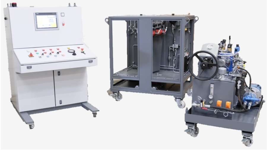
The equipment we offer is an automated and non-automated hydraulic bench composed of three sub-assemblies:
- (A) A hydraulic generation composed of a motor pump group, an oil tank with its retention tank as well as all the hydraulic components and accessories necessary for the operation of the rudder.
- (B) An operative part on a mechanically welded chassis with translucent casing, reproducing a rudder, with its instrumented control jacks, as well as opposing jacks representing the forces exerted by water on the rudder.
- (C) A control console with a power part for supplying the hydraulic generation, a command and control part, with an automaton associated with an HMI for control and display. This desk is also equipped with buttons and indicator lights.
These three assemblies are hydraulically and electrically connected to each other.
The assembly is designed to be installed in a space of 2mx2m excluding the control console.
We only use industrial components from major brands, therefore very widespread, BOSCH REXROTH or EATON VICKERS pump, TOR components Cetop 3 EATON VICKERS, WANFLUH proportional components
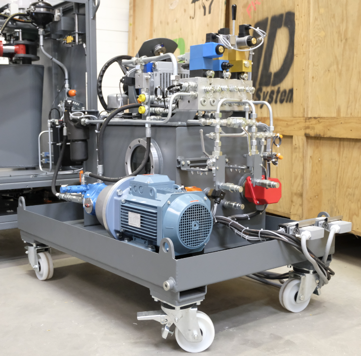
A – HYDRAULIC POWER UNIT
The hydraulic power plant is equipped with a motor pump group (3 kW motor, flow rate 10L / min at 100bar) which supplies a hydraulic bored distribution block.
This motor pump group is mounted on load with a suction valve fitted with a position sensor.
Cetop 3 components are mounted on the drilled block with standard M16x200 pressure taps in order to carry out all measurements.
The pump is a variable displacement piston pump with flow cancellation and LS regulation.
A proportional Cetop 3 distributor controls the rudder in automated mode, a position control is achieved with the return of two analog linear sensors.
A manually operated Cetop 3 distributor controls the rudder in non-automated mode.
An autonomous hydraulic bar controls the rudder in non-automated local emergency mode.
Different valves and hydraulic components provide the functions of holding in position, pressure adjustment, flow adjustment.
The tank is equipped with a fixed temperature thermostat and an adjustable temperature thermostat.
The tank is equipped with an electric low alarm level and a very low electric stop level.
An air / oil temperature exchanger cools the oil, a 3/2 valve allows the exchanger to bypass to simulate an oil temperature rise.
All hydraulic flow and pressure settings will be easily accessible on the control unit.
A 6µm absolute pressure filter and a 10µm absolute return filter with electrical clogging indicator, keeps the 46cst mineral oil clean in the cleanliness class of the most sensitive component.
A pressure switch equipped with an isolation valve transmits fault information "low pressure", the isolation valve allows to simulate a failure.
Two pressure sensors on the cylinder supply transmit the pressure value to the HMI
Components nomenclature:
- 1 painted steel tank capacity 80L
- 1 total retention tank
- 4 swivel casters
- 1 fixed thermostat 70 ° C
- 1 adjustable thermostat 10 to 90 ° C
- 1 visual level
- 1 visual dial thermometer
- 1 electric low alarm level indicator
- 1 very low level electric indicator
- 1 electric motor 3kw 230 / 400v three-phase 1500rpm with 2 temperature contacts (alarm and security)
- 1 lantern and coupling
- 1 pair of shock absorbing pads
- 1 piston pump 10 cc / rev variable displacement flow cancellation and LS
- 1 suction valve with electrical position contact
- 1 absolute 3µ pressure filter with electrical clogging indicator
- 1 absolute 10µ return filter with electrical clogging indicator
- 1 Cetop 3 bored block 3 posts
- 1 Cetop 3 bypass distributor 4/2
- 1 Cetop 3 manual control 4/3 valve
- 1 proportional distributor 4/3 Cetop 3
- 3 LS circuit selectors
- 1 Cetop 3 flow limiter on P
- 1 double piloted valve on A and B Cetop 3
- 1 double balancing valve on A and B Cetop 3
- 1 anti-shock valve on A and B Cetop 3
- 3 high pressure valves on the rudder supply
- 2 analog pressure sensors on the rudder feed
- 1 pressure switch on the P supply of the drilled block
- 1 pressure gauge
- 1 air / oil cooler
- 1 cooler bypass solenoid valve
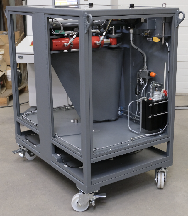
B – OPERATIVE PART STEERING SYSTEM
The operative part is composed of a mechanically welded steel frame receiving the mechanical reproduction of a rudder.
The rudder is actuated by two cylinders connected in parallel (the rod side of one cylinder with the bottom side of the other cylinder, and vice versa).
Two measurement rules control the displacement of the rudder and give the actual angular position. The two position values are compared in the PLC, a fault is sent to the automation in the event of too large a deviation. This difference can be modified artificially in the automation by the instructor to create a breakdown.
A load will be created by two opposing cylinders on the rudder to simulate the force of the water applied to the rudder. The pushing force of the cylinders will be achieved by accumulators; the hydraulic pressure will be adjustable with a hand pump used to fill the circuit.
A dial with a needle will indicate the visual position of the rudder.
An axis with an electric limit switch will allow the rudder to be locked at 0 °.
The whole is covered with translucent Lexan panels in order to visualize the movements of the rudder and the reading of the dial.
Components nomenclature:
- 1 mechanically welded painted steel chassis
- 4 swivel casters
- Translucent Lexan casing
- 1 painted steel rudder with its axis and angle indicator
- 1 0 ° locking pin with presence sensor
- 2 rudder control cylinders
- 2 analog measurement rules
- 2 accumulators
- 1 hand pump
- 2 counter cylinders
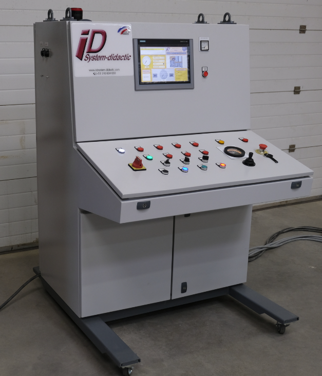
C – CONTROL DESK
The electrical cabinet is of the console type, it integrates the electrical power, and electrical control components, as well as the automation.
The electrical power part supplies the electric motors of the power unit and the chiller motor, as well as the control circuit.
A SIEMENS PLC and HMI controls the rudder in automated mode.
1 PLC assembly:
- 1 CPU315-2 PN / DP, 384 KO
- 1 S7 MICRO MEMORY CARD, 128KB
- 1 Comm. Processor CP 343-1 Lean
- 1 set of remote inputs and outputs
- 1 ET200S, IM151-1 Std, 12MBit / s
- 2 PM-E 24V
- 3 ET 200SP, DI 8x 24V DC ST
- 2 8DO 24VDC 0.5A standard
- 2 2AI I standard 4-wire 4-20 mA 12 bits, +/- 20mA 13bits
- 2 TM-P15S23-A1 screw
- 15 TM-E15S26-A1 universal screw
- 1 Panel with touch screen
- 1 SIMATIC HMI KTP1200 Basic (Profinet)
The HMI has several pages of screens for controlling and viewing the various rudder parameters, namely:
- Automatic steering angle control +/- 35 ° (+/- 37 ° in non-automated)
- Visualization of faults
- Bar angle visualization
- Circuit diagram with visualization of the working state of the components
- State of inputs and outputs
- A page "Instructor screen" for simulating failures.
The source files of the automation will be provided to you so that the pole can make any changes.
A WANDFLUH SD7 control card controls the proportional valve, the PASO software installed on a PC supplied with the bench allows the different settings of zero, gain, ramps, PID, ect ...
Different driving modes are provided depending on the position of the switches:
- Remote automated
- Remote not automated
- Automated room
- Non-automated premises
With this material, we focus on the reflection of the schematic in On/Off and proportional hydraulics (open and closed loop), on the settings by the learners of components and on the diagnosis of breakdowns.
This equipment thus highlights the different hydraulic, mechanical and automatic characteristics of a rudder.
We place the learner in a situation by reproducing a real system used on board the ships.
Components nomenclature:
- 1 music stand cabinet
- 1 general disconnector
- 1 live LED
- 1 emergency stop
- 1 group start switch
- 1 cooler engine start switch
- 1 24Vdc power supply
- 1 control circuit and power circuit protection
- 1 phase controller
- 1 needle ammeter
- 1 buzer
- 1 engine temperature fault indicator
- 1 voltage fault indicator
- 1 fault indicator for motor protection relay
- 1 emergency stop light
- 1 rudder light locked
- 1 local control light
- 1 indicator test button
- 1 group start button
- 1 group stop button
- 1 local / remote button
- 1 automated / non-automated button
- 1 switchboard switch on
- 1 Siemens S7-300 controller with Ethernet port
- 1 KTP 1200 basic 12 inch touchscreen HMI
- 1 Wandfluh SD7 amplifier card for PID control
D – LINK HOSES
The hydraulic hoses are fitted with anti-pollution couplings with valves with flat faces. This technology prevents any loss of fluid during uncoupling and any introduction of air and pollution during coupling.
ADVANTAGES: The two flat faces facilitate cleaning before coupling ensuring the protection of the hydraulic circuits. The socket is equipped with a safety locking system preventing any inadvertent opening. Automatic coupling by simple push of the male end on the female part.
3 – LAPTOP
HP Laptop
PROCESSOR: Intel Core i5 - 6200U
OPERATING SYSTEM: Windows 10
SCREEN: HD Screen SVGA BrightView WLED de 15,6 inches
RAM: 6 Go DDR3
HARD DRIVE: 1 To
Webcam with integrated microphone.
Weight : 2.04 kg
4 – SOFTWARE PROVIDED WITH THE BENCH
Configuration software for the SD7 WANFLUH PASO control card
5 – TECHNICAL DOCUMENTATION
The documentation will be provided in English in paper format in 3 copies and on digital medium (USB key) in 2 copies in Microsoft Word and PDF formats.
It will includes:
- The source files of the PLC program
- The manufacturers' documentation of the components
- Commissioning and operating instructions (Plans, diagrams, list and parts lists)
- Safety notice
- Equipment maintenance instructions
CE conformity declaration in accordance with following directives :
- "Low Voltage Directive" 2014/35/EU
- "Machinery Directive" 2006/42/EC
- "EMC Directive 2014/30/EU
- "Pressure Equipment Directive " 2014/68/EU
6 – HYDRAULIC COMMISSIONING AND AUTOMATION INSTRUCTOR TRAINING
HALF A DAY WILL BE DEDICATED TO THE EQUIPMENT INSTALLATION / PREPARATION
System and components Identification:
- Equipment description and safety instructions reading
Taking in hand:
- Accompanying of teachers for the start of the hydraulic unit and pressurization of the circuit.
- Recommendations while using the equipment
Use and equipment operation:
- Explanations and wiring of the main practical work
Preventive maintenance:
- Awareness on the fluids cleanliness.
- Control level
- Instructions for filter elements replacement
What is this?
These percentage scores are an average of 0 user reviews. To get more into detail, see each review and comments as per below
If you have used this product, support the community by submitting your review


