Double Elevator Model (DL LIFT4.0)
PL-819305
This equipment mainly trains installation, commissioning, and maintenance talents engaged in the elevator industry.
It focuses on mechanical and electronic control systems, process flows, and on cultivating students’ practical ability to solve problems and achieve the effect of drawing inferences from an example, to also find out the cause of faults quickly and accurately and eliminate them in actual work improving students’ thinking and analytical abilities.
There is an increasing demand for technical talents in related fields.
Whether it is elevator design or elevator maintenance, students or related workers need to understand the basic working principles of elevators, and in order to help students and related workers learn elevators faster, we have designed and produced the double DL LIFT4.0 elevator model.
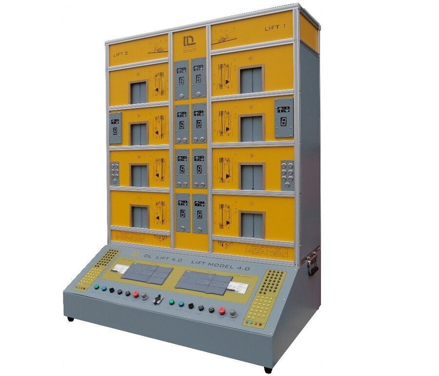
It consists of two real elevators in small scale, each with four floors and with four-stop allowing an innovative approach to PLC control and management of the multi elevator control training device understanding its principal and real use.
It shows for each elevator and for each floor with external call buttons and status displays.
It can simulate most of the building elevators encountered in daily life and its functions can basically restore the actual working scenes of most elevators.
It incorporates the logic on the PLC system to function as real common dual elevator systems like in hotels or municipal buildings and once the call button is pushed the logic on the PLC calls back the closest elevator available to the active user.
A multiplicity of sensors and motors control the presence of the cabins on each floor and the opening of both the floor and cabin doors, as in real installations, by command of the buttons inside the cabins and on the floors.
At the front of the elevator there are four automatic doors to the floors for each, with the relative floor call buttons and the elevator indicator lights.
MAIN FEATURES
- Safer - The model fully considers the user's safety at the beginning of the design and adopts excellent electrical layout reliability solutions.
- Easier to use - The structure and principle are clear and can be more convenient for users to use. It is small and has very rich functions.
- More durable - The model uses more solid and corrosion-resistant materials, which can greatly extend the service life of the equipment.
WHO IS IT FOR?
- Automation & Control Engineering,
- Mechatronics Engineering,
- Automation Technicians,
- Automatic Systems Maintenance Technicians,
- Mechatronics Technicians,
- Elevator maintenance Technicians.
In this proposed DL LIFT4.0 model, each elevator has its own independent electrical control system, drive system and car door control system including:
- Siemens PLC control operation system with possibility to communicate with a central laboratory PC,
- External call buttons,
- Four floors numbered from 1 to 4,
- Basic usage of DC drive,
- LED digital displays,
- Analog potentiometer command,
- Sensor detection,
- Positioning with photoelectric encoder,
- Automatic door opening and closing control,
- Operation as real elevator with simulation of call status and motor drive,
- Two elevator linkage operation control,
- Scada software to realize remote control function via web server.
The mechanical part of each elevator consists of a frame, guide rail, real car, counterweight, and call box with internal call buttons.
The detection signals are divided into outbound call signal, internal selection signal, levelling signal, position detection signal, door opening and closing position signal, door anti-pinch protection signal, upper and lower limit position protection signals.
Each elevator has protection functions such as switch and limit and displays the current floor position for each floor, the running direction, and the response of the outgoing call/internal call signal.
The main drive of the elevator has a DC-driven speed controlled motor simulating the actual running speed of the elevator.
The encoder of the elevator has position detection to accurately detect the position, as well as to control the acceleration and deceleration process of the elevator.
The programmable controller transmits the signals of the two elevators to the central computer for control through network communication.
It also allows the operation and the remote control of the elevators to ensure that the operator of the system has various industrial tools available to shorten operation times like in a real elevator.
It has “maintenance station” function to stop the elevator, to protect the technician during maintenance, as well as “fire station” function, to simulate the operation of the elevator in the event of a fire.
MAIN PARTS DESCRIPTION AND FUNCTION OF EACH ELEVATOR
- Outbound call display and button function board; For external display and control of floor position
- Internal call display function panel; Used to display the real-time floor location of internal calls
- Internal call button function board; Function button for internal calling
- External door of the floor elevator; Perform the opening and closing of floor elevator doors
- PLC external expansion port; Port for expanding PLC
- Circuit breaker with leakage protection device; Used to control the on and off of the circuit
- Siemens PLC and expansion module; Elevator control centre
- Manual up button; Button for manually controlling the elevator to ascend
- Manual down button; Button for manually controlling the descent of the elevator
- Manual/automatic switch knob; Knob for switching between manual and automatic
- Maintenance mode knob; Knob for entering maintenance mode
- Fire mode knob; Knob for entering fire mode
- Emergency stop switch; Used to stop the operation of the equipment in an emergency
- Elevator speed knob; Used to adjust the speed of the elevator car
- Network communication port; Port used for network communication
- Elevator car door opening and closing motor; Used to control the opening and closing of elevator car doors
- Car levelling switch; Device for detecting whether the car is aligned with the floor
- Elevator car limit switch; Limits used to limit the up and down movement of the elevator car
- Car module; Device for carrying passengers
- Elevator outer door mechanical interlock device; Device for controlling the opening and closing of elevator outer doors
- Steel cable; Steel wire rope used to pull the car
- Counterweight block; Device for balancing the weight of the car
- Encoder; Used to read the rotation parameters of the motor
- Steel cable drive fixed pulley; Pulley device for pulling the cable
- Car lift motor; Power used to control the lift
EQUIPMENT COMPONENT LIST
- Siemens S7-1200 (Control centre for elevator operation) and Expansion module.
- Siemens S7-1215C:
- DC/DC/Rly
- 14 inputs/10 outputs
- Integrated 2AI/2AO
- Expansion digital input and output module:
- SM 1223
- DI 16×24 Vdc
- DQ 16×RELAY.
- Circuit breaker with leakage protection device (Used to control the on/off of the circuit) C-type circuit breaker, suitable for circuits with single-phase AC voltage below AC 400V, rated current of 16A. It is triggered when the leakage current reaches 30mA.
- Elevator car lifting motor
- Elevator car door opening and closing motor
- Elevator car lift motor position encoder
- Elevator car position lower limit switch
- Elevator car position upper limit switch
- Elevator car door opening and closing interlock kit
- Elevator Counterweight
- Elevator floor call function panel (including buttons)
- Elevator car call button function panel
- Elevator car call display function board
- Elevator manual mode control button (buttons for controlling the elevator up and down)
- Elevator emergency stop button (for cutting off the circuit in an emergency)
- Elevator manual/automatic switch knob (used to switch between manual and automatic modes)
- Elevator operation adjustment knob (for adjusting the running speed)
- Elevators Network Communication Network (one for both elevators)
- Elevator maintenance mode switch knob
- Elevator fire mode switch knob
EXPERIMENTAL TOPICS
With this equipment, the students can perform the following experiments:
- Understand the basic structure and operation of dual elevator dynamic scheduling model.
- Demonstrate the operation of dual elevator dynamic scheduling model in manual mode.
- Demonstrate the operation of dual elevator dynamic scheduling elevator model in automatic mode.
- Demonstrate the operation of dual elevator dynamic scheduling elevator model in maintenance mode.
- Demonstrate the operation of dual elevator dynamic scheduling elevator model in fire mode.
- Demonstrate the operation speed regulation function of elevator model.
- Demonstrate the remote control and data acquisition function of dual elevator dynamic scheduling elevator model.
SUPPLIED ACCESSORIES
- Siemens programming software
- Spare limit switch
- Applications software
- Network communication cable
- Power supply cable
TECHNICAL PARAMETERS
- Input power: single-phase from mains.
- Dimensions: approx. 800mm x 610mm x 1200mm (LxDxH).
- Weight: approx. 140kg.
- Working conditions:
- Ambient temperature: -10°C ÷ +40°C,
- Relative humidity: < 85% (@25°C).
Complete with a set of practical manual and Software.
What is this?
These percentage scores are an average of 0 user reviews. To get more into detail, see each review and comments as per below
If you have used this product, support the community by submitting your review


