Automotive Auxiliary Components Unit (AV-AC)
PL-418120
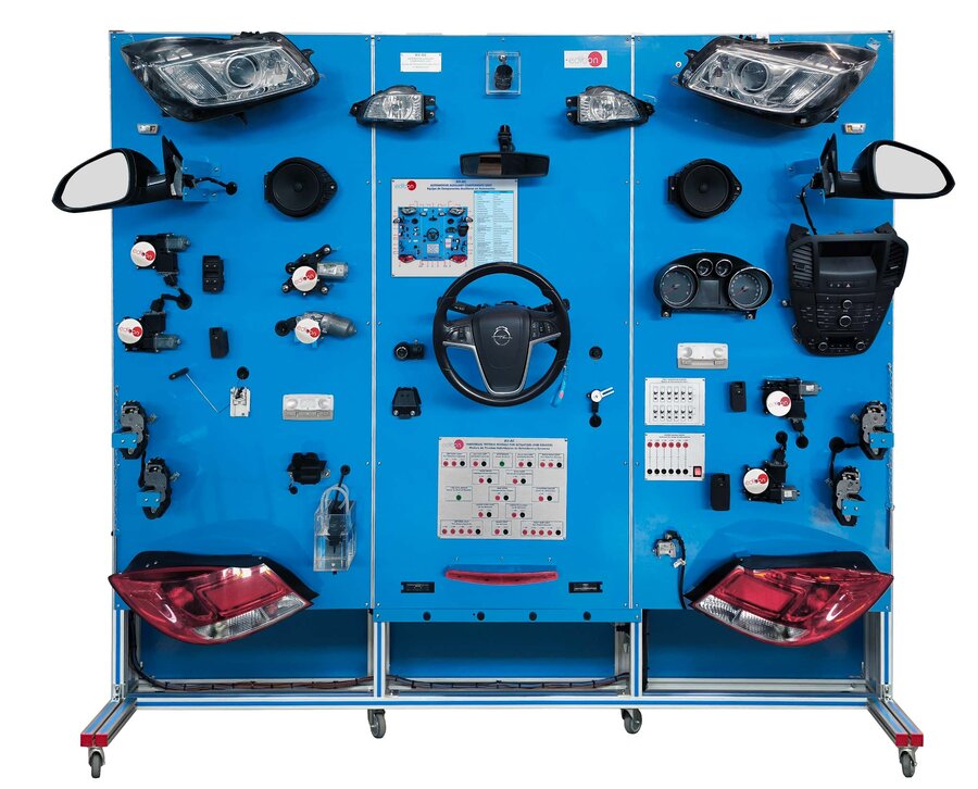
The Automotive Auxiliary Components Unit, “AV-AC”, offers a comprehensive and practical learning experience for acquiring advanced knowledge of modern electronic and electrical systems used in the automotive industry.
All sensors and actuators featured in the “AV-AC” unit are installed on individual mounting plates that include the component name, its standardized symbol, and 4 mm lab jacks for easy connection. These are real automotive components that can be linked simultaneously to the electronic control unit to simulate real-world operating conditions and system interaction.
Components can be mounted on the included vertical support frame, allowing for individual testing or complete system integration with the ECU for realistic automotive diagnostics and operation.
The included sensors and actuators cover a variety of essential automotive auxiliary systems: car lighting systems, windshield wiper and washer systems, power door lock systems, digital instrument panels, electric window systems, ultrasonic parking systems, and more. Each part is a genuine automotive-grade sensor or actuator.
Signal input and output—whether for measurements or control—is performed using analog and digital signals, PWM (Pulse Width Modulation), and CAN bus protocol, reflecting real vehicle signal communication.
Additionally, the “AV-AC” unit incorporates a fault generation module capable of simulating up to twelve different system faults, such as interruptions in the CAN bus network or errors in the 12 VDC power supply.
The “AV-AC” system comes with a comprehensive set of practical exercises designed to help students gain a solid understanding of how electronic and electric components function in today’s automotive technology.
- AV-AC. Unit:
- Electronic control system:
- Electronic control unit.
- Wiring from electronic control unit to each component.
- Fuses and relays box:
- Car GEM module.
- Operating voltage: 12 VDC.
- OBDII diagnosis connector.
- Sensor and actuator circuits:
- Power supply components:
- 12 VDC power supply to feed the system.
- Car ignition switch.
- Power door locks system:
- Remote car key.
- Front left and right electronic door locks.
- Rear left and right rear electronic door locks.
- Trunk electronic door lock.
- Electronic door lock of the fuel tank cap.
- Trunk door push-button.
- Car lightning system:
- Light sensor.
- Front lights:
- Automatic headlamp leveling system.
- Left and right low beam headlights.
- Left and right high beam headlights.
- Daytime running lights.
- Left and right front turn signals.
- Left and right side turn signals.
- Left and right front fog lights.
- Rear lights:
- Left and right rear turn signals.
- Rear fog light.
- Left and right rear brake lights.
- Third brake light.
- Reverse light.
- License plate lights.
- Auxiliary lights:
- Interior car light.
- Trunk light.
- Car lightning system:
- Rear-view mirror control switch.
- Adjustable and heated lateral rear-view mirror.
- Interior rear-view mirror with auto-dimming.
- Car instrument panel with controls:
- Tachometer.
- Speedometer.
- Fuel gauge.
- Car lightning system indicators.
- Battery charge warning indicator light.
- Oil-pressure warning indicator light.
- Light control switch:
- Low beam headlights.
- High beam headlights.
- Front fog lights switch.
- Rear fog light switch.
- Steering wheel with controls:
- Wiper washer control.
- Horn push-button.
- Emergency lights push-button.
- Reverse switch to activate the reverse light.
- Brake switch to activate the brake lights.
- Turn signals control.
- Wiper washer system:
- Rain sensor.
- Front and rear wiper washer motor.
- Washing water pump.
- Car audio system:
- Car stereo radio.
- Car stereo radio control panel.
- Two 12 VDC speakers.
- Car electric windows system:
- Left and right front electric windows motor.
- Electric windows control switches.
- CAN bus communication.
- Ultrasonic car park system:
- Four ultrasonic emitter and receiver units.
- Ultrasonic car control unit.
- 12 VDC speaker.
- Fuel level sensor.
- 12 VDC car socket.
- Heated rear window simulator.
- Test module to check the operation of each sensor and actuator working individually:
- Attached to the frame of the unit.
- 4 mm lab jack with the 12 VDC power supply.
- 4 mm lab jack with the communication terminals of the electronic control unit.
- Fault generation module:
- Attached to the frame of the unit.
- Generates twelve faults in the operation of different sensors and actuators and the communication between them and the electronic control unit.
- The faults are generated through toggle switches.
- Cables and Accessories, for normal operation.
- Manuals: This unit is supplied with the following manuals: Required Services, Assembly and Installation, Starting-up, Safety, Maintenance and Practices manuals.
EXERCISES AND PRACTICAL POSSIBILITIES TO BE DONE WITH THE MAIN ITEMS
- Familiarization with electronic control unit.
- Lighting elements and light sensor.
- Function and activation of the central locking system control components.
- Front wiper washer and rain sensor.
- Function of the adjustable and heated lateral rear-view mirror.
- Electrical window lifters system activation.
- Ultra-sonic parking system.
- Reverse light and switch.
- Brake light and switch.
- Car steering wheel control functions.
- Instrumentation panel functions.
- Activation and control of the lighting system.
- Function of the adjustable rear-view mirror with auto-dimming.
- Car audio system.
- Fault insertion and diagnosis.
- Individual testing actuators and sensors.
- Several other exercises can be done and designed by the user.
What is this?
These percentage scores are an average of 0 user reviews. To get more into detail, see each review and comments as per below
If you have used this product, support the community by submitting your review


