Automotive Electronic Control Device Unit (AV-ECD)
PL-939118
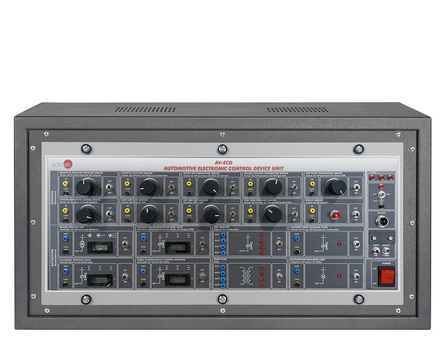
The Automotive Electronic Control Device Unit, “AV-ECD”, offers a practical solution for learning about electronic control units (ECUs) in modern vehicles.
The “AV-ECD” unit includes an Electronic Control Unit configured to operate with the emulated sensors and actuators within the system, and it can also integrate with other EDIBON units such as the Automotive Sensors Unit, “AV-S”, and the Automotive Actuators Unit, “AV-A”.
This unit features a variety of sensors and actuators simulating real automotive engine management components, including knock sensors, engine coolant sensors, Lambda sensors, camshaft position sensors, turbocharger boost control solenoids, electronic throttle valves, and engine cooling fans.
Communication between the ECU and connected components supports CAN and LIN network protocols, as well as digital and analog signals, depending on the sensor and actuator characteristics.
All sensor and actuator circuits are isolated for independent study, with multiple test points accessible through 2 mm standard lab sockets.
Fault simulation is available via toggle switches on input and output circuits, with faults indicated by the malfunction indicator lamp (MIL). The sensors and actuators can operate individually or in combination to replicate real-world scenarios.
The “AV-ECD” unit includes a comprehensive set of practical exercises, enabling students to understand the functioning, communication, and diagnostics of automotive electronic control units.
- AV-ECD”. Unit:
- Electronic control unit (ECU):
- Communication with sensors and actuators through CAN or LIN network protocols or through digital or analog signals.
- Allows self-diagnosis of the ECU to detect faults.
- Allows ECU reprogramming with two engine configurations: naturally aspirated and turbocharged.
- Emulated sensor circuits:
- Manifold absolute pressure sensor.
- Accelerator pedal position sensor.
- Intake air temperature sensor.
- Coolant temperature sensor.
- Exhaust gas recirculation (EGR) temperature sensor.
- Oxygen or Lambda sensor.
- Mass air flow sensor.
- Crankshaft and camshaft position sensors.
- Fuel tank pressure sensor.
- Emulated actuator circuits:
- Canister-purge solenoid valve.
- Turbocharger boost control solenoid.
- Exhaust gas recirculation (EGR) valve.
- Spark plug.
- Fuel injector.
- Electronic throttle valve.
- Engine refrigeration fan.
- Cables and Accessories, for normal operation.
- Manuals: This unit is supplied with the following manuals: Required Services, Assembly and Installation, Starting-up, Safety, Maintenance and Practices manuals.
EXERCISES AND PRACTICAL POSSIBILITIES TO BE DONE WITH THE MAIN ITEMS
- ECU self-diagnosis to detect faults.
- Absolute pressure sensor signal.
- Function of the fuel tank pressure sensor and the canisterpurge solenoid valve.
- Coolant temperature sensor signal.
- Function of the exhaust gas recirculation (EGR) temperature sensor.
- Function of the accelerator pedal position sensor.
- Oxygen or Lambda sensor signal.
- Mass air flow sensor signal.
- Intake air temperature sensor signal.
- Crankshaft position sensor signal.
- Camshaft position sensor signal.
- Turbocharger boost solenoid control signal.
- Function of the exhaust gas recirculation (EGR) valve.
- Understanding the electronic throttle valve function.
- Function of the fuel pump.
- Spark plug control signal.
- Fuel injector control signal.
- Engine cooling fan control signal.
- Reprogram the ECU with the atmospheric engine configuration.
- Reprogram the ECU with the turbocharged engine configuration.
What is this?
These percentage scores are an average of 0 user reviews. To get more into detail, see each review and comments as per below
If you have used this product, support the community by submitting your review


