Automotive Electric Generation Unit (AV-GE)
PL-599029
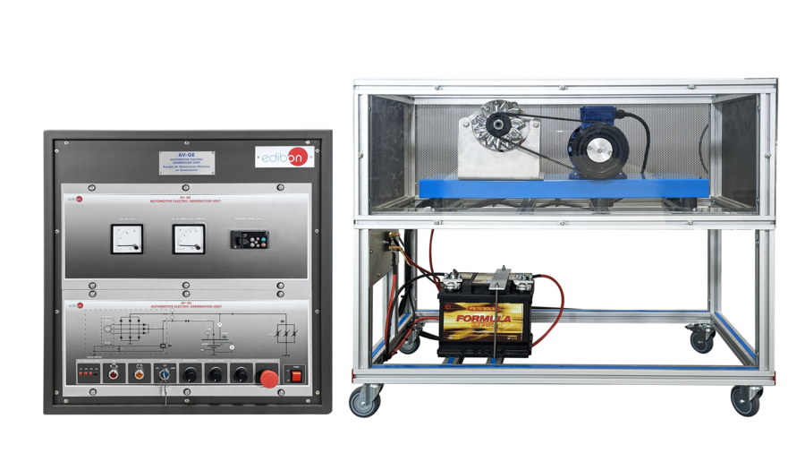
The Automotive Electric Generation Unit, “AV-GE”, designed by EDIBON, offers a practical solution to learn about the key components used in modern automotive electrical circuits.
The components of the “AV-GE” focus on electrical energy generation and automobile battery charging systems.
This unit features an engine and generator assembly connected via a belt and pulley system, replicating actual automobile operation. The generator is driven by an electric motor simulating a car’s internal combustion engine. The electrical circuit incorporates a 12 V automotive battery as the energy storage component.
Additionally, the “AV-GE” includes an instrument panel with an electric key switch and warning lights that activate during common automotive electrical faults: generator malfunction indicator (GEN-L), battery or electrical fault indicator (BATT), and malfunction indicator lamp (MIL).
The system also has an accessible fuse and relay block, enabling hands-on interaction with circuit protection and distribution elements. This facilitates fault diagnosis and enhances practical learning for technical skills development.
Beyond teaching fundamental automotive electrical principles, the “AV-GE” prepares students for hybrid and electric vehicle technologies by providing insight into energy management, integration of electrical and electronic systems, and detailed component analysis in a safe and controlled environment.
The “AV-GE” unit includes the following components:
- Instrument panel with warning lights.
- Electric key switch.
- Fuse and relay block.
- Variable frequency drive for electric motor control.
- Electric motor simulating petrol engine.
- Alternator.
- 12 VDC battery with accessible terminals.
- "AV-GE”. Unit:
- Instrument panel with the following components:
- Electric key switch.
- MIL warning light (malfunction indicator or engine check light).
- BATT warning light (battery or electrical circuit malfunction indicator).
- GEN-L warning light (electrical circuit malfunction indicator).
- Relay and fuse box:
- Automotive GEM module.
- Operating voltage: 12 VDC.
- Variable frequency drive:
- Power supply: 230 VAC.
- ON / OFF switch.
- Output voltage connections PWM: Three-phases: 230 VAC.
- Potentiometer to adjust the frequency.
- Setting and visualization display of the machine parameters.
- Electric motor for petrol engine simulation (EMT7/1K):
- Nominal power: 1100 W.
- Nominal voltage: 3 x 230/400 VAC Δ/Y.
- Frequency: 50 / 60 Hz.
- Number of poles: 2.
- Speed: 2730 rpm.
- Attached to the alternator by means of a belt and pulley system.
- Alternator:
- Nominal voltage: 12 VDC.
- Alternator charging current.
- Attached to the motor by means of a belt and pulley system.
- 12 VDC battery with accessible terminals (battery points):
- Nominal voltage: 12 VDC.
- Capacity: 62 Ah.
- Accessible terminals.
- Terminals: positive/negative.
- Cables and Accessories, for normal operation.
- Manuals: This unit is supplied with the following manuals: Required Services, Assembly and Installation, Starting-up, Safety, Maintenance and Practices manuals.
EXERCISES AND PRACTICAL POSSIBILITIES TO BE DONE WITH THE MAIN ITEMS
- Function of every element in the automotive electrical circuit.
- Operation of the alternator.
- Function of the rectifier.
- Alternator voltage adjustment.
- Ignition switch sequence.
- Features and operation of the battery.
- Operation of the electrical circuit of an automobile on battery discharge.
- Operation of the electrical circuit of an automobile on battery charge.
- Behavior of the system when an alternator failure occurs.
- Behavior of the system when a battery failure occurs.
- Behavior of the system when an internal combustion engine failure occurs.
- Several other exercises can be done and designed by the user.
What is this?
These percentage scores are an average of 0 user reviews. To get more into detail, see each review and comments as per below
If you have used this product, support the community by submitting your review


