Automotive Fundamental Electrical Circuits Unit (AV-ELC)
PL-444213
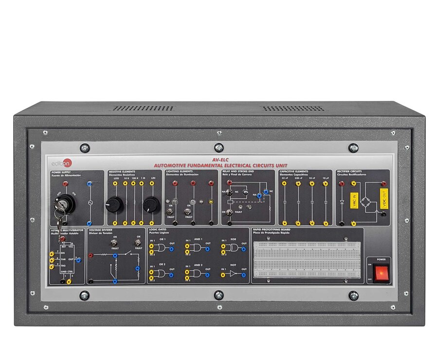
The Automotive Fundamental Electrical Circuits Unit, “AV-ELC”, provides a practical solution for learning about basic electrical circuits commonly used in modern automotive systems.
The “AV-ELC” includes a variety of circuits focused on essential automotive electrical functions, such as power supply circuits, rectifier circuits, lamp circuits, resistor circuits, capacitor circuits, and logic gate circuits. These circuits are designed to offer a comprehensive introduction to automotive electrical systems.
Each circuit in the unit is isolated to facilitate understanding of its individual operation. Multiple test points are accessible via 2 mm standard lab sockets for easy measurement and analysis.
Several circuits allow the simulation of component faults through toggle switches, helping students identify and diagnose common electrical failures.
The “AV-ELC” unit includes a series of practical exercises designed to help students grasp how fundamental automotive electrical circuits operate in real-world applications.
- AV-ELC”. Unit:
- Power supply circuit:
- 12 VCA power supply.
- 12 VCC power supply.
- Resistive elements circuit: Circuit of logarithmic potentiometers, linear potentiometers and fixed resistors with the following configurations available: in series, in parallel and mixed.
- Lighting elements circuit:
- Different lamp circuits with the following configurations available: in series and in parallel.
- LED diode.
- Relay and stroke end circuit:
- Relay circuit with a 12 VDC coil and three contacts: common, normally open and normally closed.
- End of stroke for relay control.
- Capacitive elements circuit:
- Capacitor with filter function.
- Capacitor with energy storage function.
- Rectifier circuit: Half wave and full wave rectifier circuit.
- Temporization circuit: Astable multivibrator circuit with 555IC
- Adjustable voltage divider circuit.
- Logic gates circuit: Circuit for mounting the following logic gates: NOT, AND, NAND, OR, NOR, XOR and XNOR.
- Protoboard plate:
- Protoboard plate to assemble experimental circuits without soldering.
- Components to mount a monostable multivibrator or an astable multivibrator circuit with 555IC.
- Cables and Accessories, for normal operation.
- Manuals: This unit is supplied with the following manuals: Required Services, Assembly and Installation, Starting-up, Safety, Maintenance and Practices manuals.
EXERCISES AND PRACTICAL POSSIBILITIES TO BE DONE WITH THE MAIN ITEMS
Power supply circuits:
- Waveform study in AC.
- Study of DC signals.
- Study of faults in the waveform circuit.
Load circuits:
- Resistance measurements.
- Resistance association.
- Voltage divider ratio.
- Study of faults in the resistance circuit.
- Resistance of a lamp.
- Light intensity variation.
- Turn signals temporization.
Capacitive elements circuit:
- Capacitors measurements.
- Capacitors associations.
- Study of a low-pass filter.
- Study of a high-pass filter.
- Frequency response of a low-pass filter.
- Frequency response of a high-pass filter.
Rectifier circuit:
- Study of the diode function.
- Half wave rectifier.
- Full wave rectifier.
- Study of faults in rectifier circuits.
- Full wave rectifier with filter.
Logic gates circuit:
- Study the operation with logic gates: NOT, AND, NAND, OR, NOR, XOR and XNOR.
Relay circuit:
- Study the relays terminals.
- Power supply of a DC relay coil.
- Control of a relay with a stroke end.
- Study of relay faults.
- Several other exercises can be done and designed by the user.
What is this?
These percentage scores are an average of 0 user reviews. To get more into detail, see each review and comments as per below
If you have used this product, support the community by submitting your review


