Computer Controlled Hybrid and Electric Vehicles Application (AEL-EHVC)

PL-304219
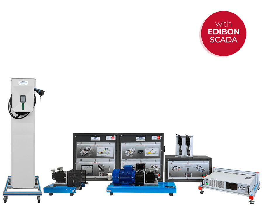
The Computer Controlled Hybrid and Electric Vehicles Application, “AEL-EHVC”, developed by EDIBON, is a cutting-edge training system designed to study and analyze the functioning and energy management of hybrid and electric vehicles, fully aligned with current and future trends in sustainable mobility and electric transportation.
Thanks to its modular configuration, the “AEL-EHVC” allows students and professionals to simulate and compare various electric vehicle (EV) and hybrid electric vehicle (HEV) architectures, providing essential skills and knowledge for evaluating energy efficiency, control strategies, and dynamic performance of modern mobility systems.
The “AEL-EHVC” application includes three different educational configurations that can be implemented independently or in combination:
100% Electric Vehicle Topology (Included):
The included configuration enables the simulation of a full electric vehicle using a regenerative DC power supply (N-DCPWS/R) that emulates the traction battery, a variable frequency drive (N-RGTR) that controls the electric motor, and a 1 kW squirrel-cage motor (EMT7B/1K-E) simulating the traction motor. Additionally, a terrain simulation servomotor reproduces driving conditions such as uphill, downhill, or flat terrain. The vehicle is controlled using an accelerator and brake pedal module, allowing users to simulate real driving actions such as acceleration, regenerative braking, and inertia rolling. The integrated SCADA software enables complete control of system parameters, battery behavior emulation (capacity, voltage curves, charging profiles), and real-time monitoring of energy consumption and regeneration.
Hybrid Vehicle Topology (Recommended – Not Included):
By integrating the N-ENGS module (Petrol Engine Simulation), the system simulates a hybrid vehicle with a servo motor and magnetic clutch representing an internal combustion engine. This allows simulation of typical hybrid operating modes where the electric motor powers the vehicle at low speeds, and the combustion engine engages at higher speeds. Users can define the torque-speed curve of the combustion engine (starting torque, maximum torque, torque at maximum speed) and configure electric assistance levels. The SCADA software dynamically manages hybrid behavior based on vehicle speed and load, simulating realistic hybrid energy transitions and assisting students in understanding complex hybrid architectures and control logic.
EV Charging Station Module (Recommended – Not Included):
The system can be expanded with a real electric vehicle charging station, enabling students to study battery charging procedures, energy flow monitoring, and charging cycle control. The SCADA system facilitates remote start/stop of charging processes and tracks parameters such as charging current, voltage, power, and state of charge (SoC). Users can analyze how different battery capacities and charger specifications affect charging times, allowing detailed study of one of the key limitations in current EV adoption.
The “AEL-EHVC” system provides a complete educational platform to explore electric and hybrid vehicle systems from a practical and theoretical standpoint, supporting the development of technical competencies in areas such as electric propulsion, hybrid drivetrain control, battery management systems (BMS), energy efficiency, and sustainable transportation technologies. Its advanced modular design and SCADA-based control and data acquisition make it an ideal tool for technical education centers, engineering faculties, vocational training institutions, and research laboratories focused on automotive and electric mobility innovation.
- AEL-EHVC. Application::
EMT7B/1K-E. 3PH Squirrel-Cage Industrial Motor, 1 kW, 4 Poles.
- Nominal power: 1000 W.
- Nominal voltage: 230 VAC / 400 VAC.
- Frequency: 50 / 60 Hz.
- Nominal load speed: 1500 rpm.
- Nominal current: 4.57 A / 2.64 A.
N-RGTR. Regenerative Powertrain Module.
- Power supply: 230 VAC.
- ON / OFF switch.
- Internal frequency drive with speed and torque control.
- Safety key “Start/Stop”.
N-DYTS. Dynamic Ground Simulation Module.
- Power supply: 400 VAC+N.
- Frequency: 50/60 Hz.
- ON / OFF switch.
- Servo motor and driver:
- Dynamic and static operating regime in four quadrants.
- Speed and torque control.
- Nominal power: 1 kW.
- Maximum power: 3 kW.
- Nominal torque: 3.18 Nm.
- Maximum torque: 9.55 Nm.
- Temperature control.
- Slope selector: uphill/flat terrain/downhill.
- % slope control potentiometer.
N-DCPWS/R. Regenerative DC Power Supply Module.
- ON / OFF switch.
- Voltage range: 0 – 350 VDC.
- Current range: 0 – 6 A.
- Power: 800 W.
- Control panel for battery mode configuration:
- Source mode.
- Charging mode.
- Integrated overcurrent protections.
- Integrated overvoltage protections.
Additional recommended elements (Not included):
N-ENGS. Petrol Engine Simulation Module.
- Power supply: 230 VAC.
- ON / OFF switch.
- Internal frequency drive with speed and torque control.
- Starter motor input signal.
- Magnetic clutch.
- Magnetic clutch control signal.
- Servo motor and driver:
- Dynamic and static operating regime.
- Speed and torque control.
- Nominal power: 1 kW.
- Maximum power: 3 kW.
- Nominal torque: 3.18 Nm.
- Maximum torque: 9.55 Nm.
- Temperature control.
EVCH. Electric Vehicle Charger.
- Basic recharge box.
- IP54 enclosure.
- Single-phase Schuko socket (230 V, 16 A, 3.6 kW).
- Single-phase energy meter (kWh).
The complete unit includes as well:
- Advanced Real-Time SCADA.
- Open Control + Multicontrol + Real-Time Control.
- Specialized EDIBON Control Software based on LabVIEW.
- National Instruments Data Acquisition board.
- Calibration exercises, which are included, teach the user how to calibrate a sensor and the importance of checking the accuracy of the sensors before taking measurements.
- Projector and/or electronic whiteboard compatibility allows the unit to be explained and demonstrated to an entire class at one time.
- Capable of doing applied research, real industrial simulation, training courses, etc.
- Remote operation and control by the user and remote control for EDIBON technical support, are always included.
- Totally safe, utilizing 4 safety systems (Mechanical, Electrical, Electronic and Software).
- Designed and manufactured under several quality standards.
- Optional ICAI software to create, edit and carry out practical exercises, tests, exams, calculations, etc. Apart from monitoring user’s knowledge and progress reached.
- This unit has been designed for future expansion and integration. A common expansion is the EDIBON Scada-Net (ESN) System which enables multiple students to simultaneously operate many units in a network.
- AEL-EHVC/CCSOF. Computer Control + Data Acquisition + Data Management Software.
- Cables and Accessories, for normal operation.
- Manuals: This unit is supplied with 7 manuals. Required services, Assembly and Installation, Control Software, Starting-up, Safety, Maintenance and Practices manuals.
EXERCISES AND PRACTICAL POSSIBILITIES TO BE DONE WITH THE MAIN ITEMS
- Detailed study of the traction system in a 100% electric vehicle: Analysis of the conversion of electrical energy into mechanical energy, evaluating the dynamic response of the three-phase motor based on acceleration and load demand.
- Comprehensive analysis of regenerative braking under different scenarios: Evaluation of kinetic energy recovery during controlled braking events and its conversion into electrical energy, monitoring the power flow regenerated back into the virtual battery.
- Dynamic evaluation of an electric vehicle’s behavior through simulated real driving cycles: Simulation of acceleration, deceleration, and constant speed patterns, replicating urban, interurban, and highway routes, and analysis of energy efficiency in each case.
- Analysis of the torque-speed relationship under different operating conditions: Study of how motor torque and speed vary according to load, acceleration, and terrain type, with graphical representation of the electric motor’s characteristic curve.
- Simulation of ascending terrain to study the traction system’s response: Analysis of the additional torque demand required on uphill slopes and its impact on energy consumption, motor efficiency, and vehicle dynamics.
- Simulation of flat terrain for the analysis of stable traction behavior: Study of energy performance under constant load conditions, evaluating motor efficiency during steady-state driving without terrain variations.
- Simulation of descending terrain and evaluation of its effect on the control and regeneration systems: Analysis of kinetic energy utilization through regenerative braking and its impact on battery recharging, depending on the simulated slope.
- Real-time graphical representation of terrain profile and its influence on vehicle behavior: Generation and monitoring of orographic profiles via SCADA, with dynamic updates of slope, speed, and power parameters.
- Analysis of power consumption under different conditions using a bidirectional battery simulator: Study of energy flows in traction and regeneration modes, evaluating the efficiency of energy conversion depending on terrain and driving cycle.
- Real-time monitoring of all key operational parameters through interactive SCADA graphs: Simultaneous visualization of critical variables such as current, voltage, power, speed, and motor torque, enabling an indepth analysis of the vehicle’s electrical system behavior.
Some practical exercises with the recommended additional element of the Petrol Engine Simulation Module (N-ENGS):
- Study of the combined operation of the electric and combustion engines in a hybrid vehicle: Analysis of the dynamic coordination between both energy sources, evaluating power distribution and overall efficiency under various driving conditions.
- Visualization and analysis of the magnetic clutch coupling to the main traction system: Observation of the controlled connection process between the combustion engine and the electric motor, assessing the real-time transition between operating modes.
- Graphical analysis of torque transmission during the coupling process: Interactive graphical representation of the motor torque behavior at the moment the combustion engine couples to the traction system.
- Monitoring the automatic synchronization process between the combustion and electric motors: Real-time monitoring of both motors’ speed and torque during automatic synchronization, evaluating transition efficiency and smoothness.
- Evaluation of electric and combustion motor participation under different terrain conditions in automatic mode: Study of the vehicle’s adaptive behavior on ascending, flat, and descending terrains, with automatic management of the participation percentages of each motor.
- Study of motor coupling and clutch control in manual mode: Manual configuration of motor coupling/decoupling, allowing experimentation and analysis of customized energy management strategies.
- Simulation of ascending terrain for parallel hybrid vehicles: Analysis of the hybrid system’s response to increasing slopes, evaluating the combined effort of both motors and the impact on energy consumption.
- Simulation of descending terrain for parallel hybrid vehicles: Study of regenerative capacity and energy management during downhill conditions, analyzing the interaction between regenerative braking and combustion engine decoupling.
- Configuration and analysis of the electric motor’s response to sudden accelerations: Adjustment of accelerator pedal sensitivity parameters and evaluation of the electric motor’s response during high instantaneous power demand.
- Study of in-motion battery recharging through electric motor drag by the combustion engine: Analysis of electrical energy generation when the battery is at low charge levels, simulating the typical in-motion recharging mode of hybrid vehicles.
- Integration and comparative analysis of different combustion engine torque-speed maps: Programming and evaluation of various combustion engine performance curves, assessing their effect on hybrid vehicle efficiency and dynamics.
- Modification of control parameters related to motor participation: Adjustment of advanced functions such as generation mode activation at low battery levels and accelerator pedal sensitivity, optimizing the hybrid strategy.
- Comparison of energy efficiency between a 100% electric vehicle and a parallel hybrid vehicle: Comparative analysis based on energy consumption, range, and dynamic behavior, evaluating the advantages and disadvantages of each technology under real operating conditions.
Some practical exercises with the recommended additional element of the with the Electric Vehicle Charger (EVCH):
- Simulation of a realistic charging process using a real electric vehicle charger: Reproduction of a real-world charging cycle by connecting a commercial-type charger to the system, allowing the study of the initiation, continuous charging, and completion phases under realistic conditions.
- Physical connection and validation of the link between the charger and the traction system: Execution of the physical connection of the electric charger to the equipment, verification of communication between devices, and monitoring of the automatic activation of the charging protocol.
- Measurement and analysis of electrical parameters during the charging process: Real-time monitoring of voltage, charging current, and supplied power, evaluating the electrical behavior of the system throughout the different stages of the charging process.
- Evaluation of charging times based on the battery capacity set in SCADA: Study of the time required to reach specific charge levels, analyzing how the defined battery capacity directly influences the total charging time.
- Analysis of the influence of C-Rate on charging process efficiency: Evaluation of the impact of different C-Rates on the total charging time, assessing the relationship between charge rate, battery characteristics, and energy management efficiency.
What is this?
These percentage scores are an average of 0 user reviews. To get more into detail, see each review and comments as per below
If you have used this product, support the community by submitting your review


