PL-610674
Reviews
Not reviewed yet
Producer
Content languages
English , Spanish
Certification labels
UL , CE
Warranty
60
Producer product code
EESFC
Solar PV

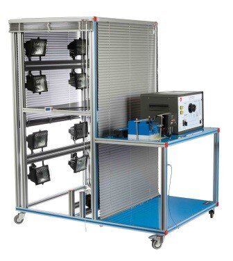
The Computer Controlled Photovoltaic Solar Energy Unit, "EESFC", includes equipment that uses the photo-conversion law for the direct conversion of solar radiation into electricity. The absorbed energy is provided by simulated solar radiation, which in our case is supplied by a panel with powerful light sources (solar lamps).

The unit contains:

  • Photovoltaic solar panels.
  • Solar simulator composed of solar lamps.
  • Ventilation system.
  • DC load and battery charger regulator.
  • Auxiliary battery charger.
  • Battery.
  • DC Loads module.
  • Sensors (temperature, light radiation, DC current and DC voltage).
  • This Computer Controlled Unit is supplied with the EDIBON Computer Control System
  • (SCADA), and includes: The unit itself + a Control Interface Box + a Data Acquisition Board + Computer Control, Data Acquisition and
  • Data Management Software Packages, for controlling the process and all parameters involved in the process.


Optional (NOT included in the minimum supply):

  • EE-KIT. Kit of Conversion and Consumption Simulation (AC):
  • Single-phase inverter.
  • AC Loads Module:
  • 3 Lamps, 1 axial compact fan with plastic guards and 4 positions selector.
  • AC voltage and current sensors.
  • EE-KIT2. Grid Connection Inverter Kit:
  • Grid Connection Inverter.
  • Grid Simulator (ESR).


With this unit there are several options and possibilities:
- Main items: 1, 2, 3, 4, 5 and 6.
- Optional items: 7, 8, 9, 10 and 11.
Let us describe first the main items (1 to 6):
1. EESFC. Unit:
The “EESFC” unit is a computer controlled unit for the study of the conversion of solar energy into electric energy.
Anodized aluminum frame and panels made of painted steel.
The unit includes wheels to facilitate its mobility.
Main metallic elements made of stainless steel.
Diagram in the front panel with distribution of the elements similar to the real one.
The unit includes:
Two photovoltaic solar panels (polycrystalline):
Tempered glass modules with high level of transmissivity.
Encapsulating material: modified ethylene-vinyl acetate.
Output nominal power: 66 W.
Area of the panel: 0.51 m².
Max. current: 3.76 A. Max. voltage: 17.53 V.
Thirty six cells, 156 x 156 mm each.
Solar simulator composed of:
Aluminum frame.
Eight halogen lamps of 400W each one, distributed into two independent voltage regulated circuits.
Electrically safe.
Ventilation system, computer controlled, that allows to analyze the temperature influence on the unit operation, formed by:
Four axial compact fans with plastic guards.
DC load and battery charger regulator:
It regulates how power generated in the photovoltaic solar panels is distributed to and from the auxiliary battery and to the load. A display informs about the state of the charge, operating parameters and fault messages. The functions of the electronic protection are:
Overvoltage disconnection, short circuit protection of load and module, overvoltage protection at module input, over-temperature and overload protection, and battery overvoltage shutdown.
Auxiliary battery charger:
It carefully assesses the battery and then delivers the optimum charge required.
Battery:
Nominal voltage: 12 V. Rated capacity (20 hours rate): 24A/H.
DC loads module:
Metallic box with diagram on the front panel.
Two lamps of 24 V.
DC motor: voltage: 36V, power: 5W.
Rheostat of 500W.
Independent connection for every load with the help of the 4 positions selector:
Solar panels work at open-circuit.
Rheostat and lamps are connected directly to the solar panels. These loads can be connected individually or in parallel with the aid of manual switches.
The DC motor is directly connected to the solar panels.
The DC load is disconnected and the solar panels are directly connected to the charge regulator.
Sensors:
Solar radiation sensor to study the behaviour of solar photovoltaic panels.
Three “J” type temperature sensors to measure the environmental temperature, the temperature in the solar panel no. 1 and the temperature in the solar panel no. 2.
DC current sensor and DC voltage sensor. The value of DC power can be visualized with the software.
The connection of solar panels in parallel or series, the measurement of the voltage and the current before or after the regulator and the regulation of the light intensity of lamps of the two independent circuits are computer controlled. The unit includes four blinds to reduce a direct visual contact with the halogen lamps and to reduce the direct contact with the photovoltaic solar panels when the unit is working.
Optional (NOT included with the minimum supply): See the “Optional” section on page 6.
- EE-KIT. Kit of Conversion and Consumption Simulation (AC):
Single-phase inverter.
AC Loads module:
Three lamps, axial compact fan with plastic guards and 4 positions selector.
AC voltage and current sensors.
- EE-KIT2. Grid Connection Inverter Kit:
Grid Connection Inverter.
Grid Simulator (ESR).
The complete unit includes as well:
Advanced Real-Time SCADA.
Open Control + Multicontrol + Real-Time Control.
Specialized EDIBON Control Software based on LabVIEW.
National Instruments Data Acquisition board (250 KS/s, kilo samples per second).
Calibration exercises, which are included, teach the user how to calibrate a sensor and the importance of checking the accuracy of the sensors before taking measurements.
Projector and/or electronic whiteboard compatibility allows the unit to be explained and demonstrated to an entire class at one time.
Capable of doing applied research, real industrial simulation, training courses, etc.
Remote operation and control by the user and remote control for EDIBON technical support, are always included.
Totally safe, utilizing 4 safety systems (Mechanical, Electrical, Electronic & Software).
Designed and manufactured under several quality standards.
Optional ICAI software to create, edit and carry out practical exercises, tests, exams, calculations, etc. Apart from monitoring user's knowledge and progress reached.
This unit has been designed for future expansion and integration. A common expansion is the EDIBON Scada-Net (ESN) System which enables multiple students to simultaneously operate many units in a network.
2. EESFC/CIB. Control Interface Box:
The Control Interface Box is part of the SCADA system.
Control interface box with process diagram in the front panel and with the same distribution that the different elements located in the unit, for an easy understanding by the student.
All sensors, with their respective signals, are properly manipulated from -10V. to +10V. computer output.
Sensors connectors in the interface have different pines numbers (from 2 to 16), to avoid connection errors.
Single cable between the control interface box and computer.
The unit control elements are permanently computer controlled, without necessity of changes or connections during the whole process test procedure.
Simultaneous visualization in the computer of all parameters involved in the process.
Calibration of all sensors involved in the process.
Real time curves representation about system responses.
Storage of all the process data and results in a file.
Graphic representation, in real time, of all the process/system responses.
All the actuators’ values can be changed at any time from the keyboard allowing the analysis about curves and responses of the whole process.
All the actuators and sensors values and their responses are displayed on only one screen in the computer.
Shield and filtered signals to avoid external interferences.
Real time computer control with flexibility of modifications from the computer keyboard of the parameters, at any moment during the process.
Real time computer control for pumps, compressors, heating elements, control valves, etc.
Real time computer control for parameters involved in the process simultaneously.
Open control allowing modifications, at any moment and in real time, of parameters involved in the process simultaneously.
Three safety levels, one mechanical in the unit, another electronic in the control interface and the third one in the control software.
3. DAB. Data Acquisition Board:
The Data Acquisition board is part of the SCADA system.
PCI Express Data acquisition board (National Instruments) to be placed in a computer slot. Bus PCI Express.
Analog input:
Number of channels= 16 single-ended or 8 differential. Resolution=16 bits, 1 in 65536.
Sampling rate up to: 250 KS/s (kilo samples per second).
Input range (V)=±10 V. Data transfers=DMA, interrupts, programmed I/0. DMA channels=6.
Analog output:
Number of channels=2. Resolution=16 bits, 1 in 65536.
Maximum output rate up to: 900 KS/s.
Output range (V)=±10 V. Data transfers=DMA, interrupts, programmed I/0.
Digital Input/Output:
Number of channels=24 inputs/outputs. D0 or DI Sample Clock frequency: 0 to 100 MHz.
Timing: Number of Counter/timers=4. Resolution: Counter/timers: 32 bits.
4. EESFC/CCSOF. Computer Control + Data Acquisition + Data Management Software:
The three softwares are part of the SCADA system.
Compatible with actual Windows operating systems. Graphic and intuitive simulation of the process in screen. Compatible with the industry standards.
Registration and visualization of all process variables in an automatic and simultaneous way.
Flexible, open and multicontrol software, developed with actual windows graphic systems, acting simultaneously on all process parameters.
Management, processing, comparison and storage of data.
Sampling velocity up to 250 KS/s (kilo samples per second).
Calibration system for the sensors involved in the process.
It allows the registration of the alarms state and the graphic representation in real time.
Comparative analysis of the obtained data, after the process and modification of the conditions during the process.
Open software, allowing the teacher to modify texts, instructions. Teacher’s and student’s passwords to facilitate the teacher’s control on the student, and allowing the access to different work levels.
This unit allows the 30 students of the classroom to visualize simultaneously all the results and the manipulation of the unit, during the process, by using a projector or an electronic whiteboard.
5. Cables and Accessories, for normal operation.
6. Manuals:
This unit is supplied with 8 manuals: Required Services, Assembly and Installation, Interface and Control Software, Starting-up, Safety, Maintenance, Calibration & Practices Manuals.
References 1 to 6 are the main items: EESFC + EESFC/CIB + DAB + EESFC/CCSOF + Cables and Accessories + Manuals are included in the minimum supply for enabling normal and full operation.Optional
EE-KIT. Kit of Conversion and Consumption Simulation (AC):
 Single-phase inverter:
 Single-phase. 25 kHz switch mode technology. Start-up power of 200 %. Short-circuit protection. High temperature protection. Overcharge protection.
 Operation state indicating LED. Rear connection/disconnection switch.
 AC Loads Module:
 Metallic box. Diagram in the front panel.
 Axial compact fan of 230 V with plastic guards.
 3 Lamps of 220V – 240 V, power: 11W.
 Independent connection for every load with the help of the 4 positions selector:
 -Inverter operation with no load.
 -Fan motor connected.
 -One AC lamp connected.
 -Two AC lamps connected in parallel.
 AC voltage and current sensor. The value of AC power can be visualized with the software.

EE-KIT2. Grid Connection Inverter Kit:
 Inverter used for the conversion and injection to the grid of the power generated by a simulated source of renewable energy. The simulated source is a simulator used to obtain a variable power to be injected to the grid.
 The operation mode is displayed by means of an indicating LED at the front side of the housing.
It is equipped with extensive safety measures to ensure that it is immediately switched off as soon as the AC plug is removed from the wall socket or the operation of the public grid fails.
 The inverter can be connected to a computer (PC) through a RS232 communication to display some parameters, such as voltage and current inputs, mains voltage and frequency, maximum AC power, Kwh, etc.
Grid Connection Inverter:
  Input (DC):
  Nominal power @ 25 ºC: 150 W. Maximum power @ 25 ºC: 220 W. MPP voltage: 45-125 V DC. Maximum voltage: 155 V DC.
  Nominal current: 3A.
  Output (AC):
  Voltage: 230 V (207 - 253 V). Maximum power, fuse: 2.25 A. Frequency: 50 Hz (49.8 ~ 50.2 Hz).
 This unit is supplied with the Grid Simulator (ESR), which simulates a low power grid to inject the power generated by the inverter.

 Grid Simulator (ESR):
 ESR is designed to create an isolated low power grid. The unit uses a battery as voltage source and generates a sine signal of 220V/50Hz. The main features of the ESR are:
 Inlet voltage source: battery of 12Vdc. Output: 220V/50Hz. Isolation transformer.  Battery charger included.  Protection fuses.
     The user can work with this module safely. The devices included in the EE-KIT2 can be used worldwide.
 

TENDER SPECIFICATIONS (for optional items)

a) Industrial configuration
7 PLC. Industrial Control using PLC (it includes PLC-PI Module plus PLC-SOF Control Software):
 -PLC-PI. PLC Module:
  Metallic box.
  Circuit diagram in the module front panel.
  Digital inputs (X) and Digital outputs (Y) block: 16 Digital inputs. 14 Digital outputs.
  Analog inputs block: 16 Analog inputs.
  Analog outputs block: 4 Analog outputs.
  Touch screen.
  Panasonic PLC:
      High-speed scan of 0.32 µsec. Program capacity of 32 Ksteps. High-speed counter. Multi-point PID control.
  Digital inputs/outputs and analog inputs/outputs Panasonic modules.
 -EESFC/PLC-SOF. PLC Control Software:
  For this particular unit, always included with PLC supply.
Practices to be done with PLC-PI:
1.-  Control of the particular unit process through the control interface box without the computer. 
2.-  Visualization of all the sensors values used in the particular unit process. 
3.-  Calibration of all sensors included in the particular unit process. 
4.-  Hand on of all the actuators involved in the particular unit process. 
5.-  Realization of different experiments, in automatic way, without having in front the particular unit. (These experiments can be decided previously). 
6.-  Simulation of outside actions, in the cases do not exist hardware elements. (Example: test of complementary tanks, complementary industrialenvironment to the process to be studied, etc). 
7.-  PLC hardware general use. 
8.-  PLC process application for the particular unit. 
9.-  PLC structure. 
10.-PLC inputs and outputs configuration. 
11.-PLC configuration possibilities. 
12.-PLC program languages. 
13.-PLC different programming standard languages (ladder diagram (LD), structured text (ST), instructions list (IL), sequential function chart (SFC), function block diagram (FBD)). 
14.-New configuration and development of new process. 
15.-Hand on an established process. 
16.-To visualize and see the results and to make comparisons with the particular unit process. 
17.-Possibility of creating new process in relation with the particular unit. 
18.-PLC Programming Exercises. 
19.-Own PLC applications in accordance with teacher and student requirements.

b) Technical and Vocational Education configuration
8 EESFC/ICAI. Interactive Computer Aided Instruction Software System.
This complete software package consists of an Instructor Software (EDIBON Classroom Manager - ECM-SOF) totally integrated with the Student Software (EDIBON Student Labsoft - ESL-SOF). Both are interconnected so that the teacher knows at any moment what is the theoretical and practical knowledge of the students.
- ECM-SOF. EDIBON Classroom Manager (Instructor Software).
ECM-SOF is the application that allows the Instructor to register students, manage and assign tasks for workgroups, create own content to carry out Practical Exercises, choose one of the evaluation methods to check the Student knowledge and monitor the progression related to the planned tasks for individual students, workgroups, units, etc...so the teacher can know in real time the level of understanding of any student in the classroom.
Innovative features:
• User Data Base Management.
• Administration and assignment of Workgroup, Task and Training sessions.
• Creation and Integration of Practical Exercises and Multimedia Resources.
• Custom Design of Evaluation Methods.
• Creation and assignment of Formulas & Equations.
• Equation System Solver Engine.
• Updatable Contents.
• Report generation, User Progression Monitoring and Statistics.
- ESL-SOF. EDIBON Student Labsoft (Student Software).
ESL-SOF is the application addressed to the Students that helps them to understand theoretical concepts by means of practical exercises and to prove their knowledge and progression by performing tests and calculations in addition to Multimedia Resources. Default planned tasks and an Open workgroup are provided by EDIBON to allow the students start working from the first session. Reports and statistics are available to know their progression at any time, as well as explanations for every exercise to reinforce the theoretically acquired technical knowledge.
Innovative features:
• Student Log-In & Self-Registration.
• Existing Tasks checking & Monitoring.
• Default contents & scheduled tasks available to be used from the first session.

• Practical Exercises accomplishment by following the Manual provided by EDIBON.
• Evaluation Methods to prove your knowledge and progression.
• Test self-correction.
• Calculations computing and plotting.
• Equation System Solver Engine.
• User Monitoring Learning & Printable Reports.
• Multimedia-Supported auxiliary resources.

9 EESFC/FSS. Faults Simulation System.
Faults Simulation System (FSS) is a Software package that simulates several faults in any EDIBON Computer Controlled Unit.
The "FAULTS" mode consists in causing several faults in the unit normal operation. The student must find them and solve them.
There are several kinds of faults that can be grouped in the following sections:
    Faults affecting the sensors measurement:
    - An incorrect calibration is applied to them.
    - Non-linearity.
    Faults affecting the actuators:
    - Actuators channels interchange at any time during the program execution.
    - Response reduction of an actuator.
    Faults in the controls execution:
    - Inversion of the performance in ON/OFF controls.
    - Reduction or increase of the calculated total response.
    - The action of some controls is annulled.
    On/off faults:
    - Several on/o    - Several on/off faults can be included.

c) Multipost Expansions options
10 MINI ESN. EDIBON Mini Scada-Net System for being used with EDIBON Teaching Units.
MINI ESN. EDIBON Mini Scada-Net System allows up to 30 students to work with a Teaching Unit in any laboratory, simultaneously.
The MINI ESN system consists of the adaptation of any EDIBON Computer Controlled Unit with SCADA integrated in a local network.
This system allows to view/control the unit remotely, from any computer integrated in the local net (in the classroom), through the main computer connected to the unit.
Main characteristics:
- It allows up to 30 students to work simultaneously with the EDIBON Computer Controlled Unit with SCADA, connected in a local net.
- Open Control + Multicontrol + Real Time Control + Multi Student Post.
- Instructor controls and explains to all students at the same time.
- Any user/student can work doing "real time" control/multicontrol and visualisation.
- Instructor can see in the computer what any user/student is doing in the unit.
- Continuous communication between the instructor and all the users/students connected.
Main advantages:
- It allows an easier and quicker understanding.
- This system allows you can save time and cost.
- Future expansions with more EDIBON Units.
The system basically will consist of:
This system is used with a Computer Controlled Unit.
- Instructor’s computer.
- Students’ computers.
- Local Network.
- Unit-Control Interface adaptation.
- Unit Software adaptation.
- Webcam.
- MINI ESN Software to control the whole system.
- Cables and accessories required for a normal operation.
ff faults can be included.

c) Multipost Expansions options
10 MINI ESN. EDIBON Mini Scada-Net System for being used with EDIBON Teaching Units.
MINI ESN. EDIBON Mini Scada-Net System allows up to 30 students to work with a Teaching Unit in any laboratory, simultaneously.
The MINI ESN system consists of the adaptation of any EDIBON Computer Controlled Unit with SCADA integrated in a local network.
This system allows to view/control the unit remotely, from any computer integrated in the local net (in the classroom), through the main computer connected to the unit.
Main characteristics:
- It allows up to 30 students to work simultaneously with the EDIBON Computer Controlled Unit with SCADA, connected in a local net.
- Open Control + Multicontrol + Real Time Control + Multi Student Post.
- Instructor controls and explains to all students at the same time.
- Any user/student can work doing "real time" control/multicontrol and visualisation.
- Instructor can see in the computer what any user/student is doing in the unit.
- Continuous communication between the instructor and all the users/students connected.
Main advantages:
- It allows an easier and quicker understanding.
- This system allows you can save time and cost.
- Future expansions with more EDIBON Units.
The system basically will consist of:
This system is used with a Computer Controlled Unit.
- Instructor’s computer.
- Students’ computers.
- Local Network.
- Unit-Control Interface adaptation.
- Unit Software adaptation.
- Webcam.
- MINI ESN Software to control the whole system.
- Cables and accessories required for a normal operation.


Voltage availability
100-127V, 220-240V
Production lead time
105 days
Teacher materials available
Yes
Student materials available
Yes
E-Learning modules
Yes

Similar products

Best products in this category
The EN 01.6 equipment scales a complete photovoltaic solar system. It has been designed with special
Solar PV
Content languages
English , Spanish
Add to quotation list
Modular trainer for the theoretical and practical study of the electrical installations with photovo
Solar PV Wind Energy
Content languages
English , Italian , Spanish , French
Add to quotation list
The Photovoltaic Systems Application in Isolated and Parallel Grids, ''AEL-PHIP'', has been designed
Solar PV
Content languages
English , Spanish
Add to quotation list
The equipment EN 01.4 has been designed as a standalone photovoltaic solar power plant, with 2 modul
Solar PV
Content languages
Spanish , English
Add to quotation list