Microgrid Power Systems (AEL-MGP)

PL-826478
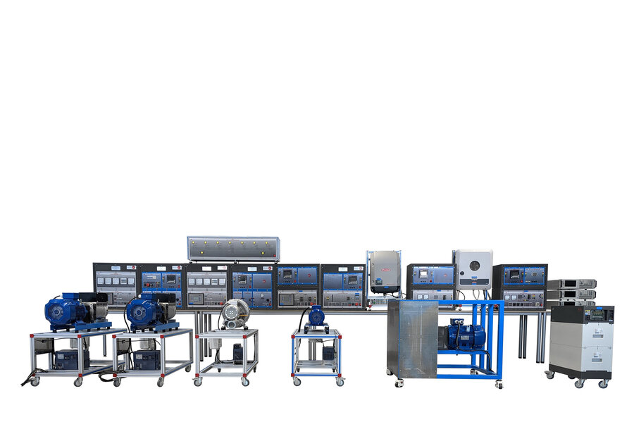
The Microgrid Power Systems training equipment, “AEL-MGP”, has been developed by EDIBON to provide both theoretical and practical training in microgrid power systems.
In today’s global energy context, microgrids play a fundamental role in the transformation of electrical infrastructure. These systems make possible the local integration of renewable energy sources, intelligent energy demand management, and storage solutions, ensuring energy autonomy and supply continuity even during main grid failures or disconnections.
They also contribute to the reduction of greenhouse gas emissions and to the democratization of energy access, particularly in rural or isolated environments.
In response to these growing needs, EDIBON has carefully designed the “AEL-MGP” as a complete and practical educational tool, enabling users to simulate, evaluate, and understand the real operation of a hybrid microgrid.
EDIBON’s focus on educational innovation is evident in every aspect of the “AEL-MGP”: modular structure, industrial-grade components, high durability and safety, more than 70 practical exercises, and the ability to adapt to specific academic curricula or research projects.
With the “AEL-MGP” unit, instructors and professionals can explore advanced topics such as island mode operation, hierarchical energy management (energy mix), dynamic stability, power quality, black start procedures, reverse power flow analysis, power balance and distribution, blackout simulation, and the implementation of Grid-Forming and Grid-Following control strategies, among others.
Ultimately, this system is not only part of the energy transition—it also trains the professionals who will lead it.
- PWP-CE. Conventional Energy Power Plant.
Its function, as in a real microgrid, is to serve as the structural foundation of the system and to provide voltage and frequency references. The rest of the power plants synchronize to it due to the stability it offers.
Additionally, this application operates as base-load generation, delivering continuous power supply. In real microgrids, this role is typically fulfilled by diesel or gas-powered systems.The setup includes a turbine-generator assembly consisting of an electric motor (simulating the turbine) mechanically coupled to a three-phase synchronous generator for electrical energy generation.
A multifunction digital controller (AVR and ASC) manages the turbine-generator unit, allowing accurate control of both mechanical and electrical parameters. The key control variables include turbine speed, generator frequency, excitation current, voltage, and electrical power output (active P, reactive Q, and apparent S). This control module also features advanced generator and turbine protection functions in accordance with ANSI standards such as ANSI 81O, 81U, 59, 27, 50/51, 32R/F, IOP 32, MOP 32, 46, voltage asymmetry, generator ground fault, phase rotation, IEC 255, and lagging power factor, among others.
The system also includes smart metering-compatible network analyzers for monitoring generated and consumed energy, with two-way communication capability for optimized system management.
- PWP-HE. Hydroelectric Power Plants.
The purpose of this application is to study hydroelectric power plants within the framework of microgrid systems. Hydroelectric plants offer a high capacity for supplying energy during peak demand due to their fast response times, making them a valuable element in intelligent energy distribution.
This application features a turbine-generator set designed to deliver power to the microgrid based on operator (user) decisions, and includes a network analyzer for real-time monitoring of the energy produced. A multifunction digital controller (AVR and ASC) manages the turbine-generator group, enabling optimal regulation of electrical and mechanical parameters, including active power reference control to determine the exact amount of power injected into the grid and coordinate energy sharing across generators.
- PWP-WE. Wind Power Plants.
The purpose of this application is to study wind power plants within the context of microgrids. It features an induction turbine-generator unit designed to supply energy to the microgrid, enabling intelligent energy distribution based on the operator’s (user’s) decisions. The system includes a network analyzer for real-time measurement of the energy produced by the wind turbine.
Additionally, a multifunction digital controller (AVR and ASC) manages the turbine-generator unit, providing optimal regulation of all electrical and mechanical parameters, including the ability to set the active power reference point, which automatically determines the amount of power injected into the microgrid.
- PWP-PE. Phototvoltaic Power Plants.
The purpose of this application is to study photovoltaic power plants within the context of microgrids. It includes a three-phase inverter powered by a photovoltaic panel array simulator, allowing the user to configure generation parameters and functions according to the scenarios and conditions being analyzed. At the same time, the application enables the study of key photovoltaic concepts such as MPPT (maximum power point tracking), inverter power limitation (derating), inverter efficiency, and reactive power generation.
- PWP-BE. Batteries Energy Storage Power Plant.
The purpose of this application is to demonstrate the importance of energy storage in isolated environments. In situations where wind or photovoltaic energy is unavailable, chemical energy storage using batteries becomes essential.
This application features a bidirectional inverter designed to store energy in the included battery and to supply it rapidly when demand arises. Thanks to the use of power electronics, this system offers a high response speed, allowing power plants such as hydroelectric or wind farms sufficient time to adjust to sudden changes in energy demand by storing surplus energy during periods of overproduction.
- PWP-FE. Flywheel Storage Power Plant.
The purpose of this application is to demonstrate the importance of energy storage in isolated environments. This advanced system stores kinetic energy using a flywheel and includes a bidirectional converter that enables energy to be absorbed from the microgrid and returned when needed. Thanks to the power electronics involved, the system offers a very fast response time, providing power plants like hydroelectric or wind farms sufficient time to respond to sudden changes in energy demand.
The “AEL-MGP” application includes a real-time supervision, control, and data acquisition SCADA software (EMG-SCADA), designed to represent and manage microgrid operations. This system enables remote and centralized control of each generation plant—both conventional and renewable—along with energy storage and system loads. Key features include configuration of plant parameters, adjustment of frequency (f), voltage (V), and power (P) setpoints, automatic grid synchronization, energy quality monitoring, load flow tracking, and the creation of dynamic demand and renewable resource profiles. Thanks to its intuitive graphical interface and high interactivity, the SCADA software allows simulation of real operational scenarios, faults, imbalances, and energy optimization strategies, making it an essential tool for technical training and validation of complex electrical systems.
- AEL-MGP. Systems :
The Conventional Power Plant, “PWP-CE”, includes the following elements:
N-ALI12. Power Supply Module with Phase Sensor 3PH+N/400 VAC.
- Supply voltage: 400 VAC, 3PH + N.
- ON/OFF removable key.
- Output voltage connections:
- Three-phase + Neutral: 400 VAC.
- Single-phase: 230 VAC
- Three-phase supply hose with IP44 3PN+E 32 A 400 V connecting plug.
- Differential magnetothermal 4 poles, 25 A, 30 mA AC 6 KA.
- Emergency stop push-button.
GMG4.5K3PH. 4.5 kW Generator-Motor Group.
- Motor-generator group coupled in an aluminum frame with wheels.
N-EALD/M. Power Network Analyzer with Modbus TCP/IP Module.
- This network analyzer module allows measurement, visualization, and analysis of all electrical parameters in AC electrical networks. It features an LCD screen and navigation buttons for the menus. Includes specialized software for monitoring voltage and current waveforms, harmonic visualization, tariff programming, alarm programming, and storage of electrical parameters.
- Features:
- Multifunctional three-phase power meter:
- Three-phase and single-phase voltage. Up to 690 VAC L-L.
- Line and neutral nominal current: 10 A.
- Active, reactive and apparent power.
- Suitable frequencies: 25 Hz, 50 Hz, 60 Hz and 400 Hz.
- Display of the V-I vector diagram.
- Supply voltage: 85 – 265 VAC.
- Powerquality control:
- Measurement of individual current and voltage harmonics up to the 40th harmonic.
- Voltage and current THD, TDD, and K-Factor.
- Maximum and minimum value display.
- Waveformdisplay, 128 samples/sec.
- Events and data storage:
- Harmonic analyzer:
- Voltage and current THD, current TDD and K-Factor, up to the 40th harmonic.
- Harmonic spectrum and phase angles for current and voltage.
- Tariff programming:
- Class 0.5S IEC 62053 – 22, active and reactive power in four quadrants.
- Measurement of the total and per phase three-phase active, reactive and apparent powers.
- Usage time, four energy/demand records of total tariffs.
- Eight tariffs, four seasons and four types of days.
- Automatic daily report of energy consumption maximums and minimums.
- Communications:
- Modbus TCP/IP communication port.
GEC-KIT-1. Generator Excitation Circuit Kit 1.
N-AVR/P. Automatic Voltage Regulator Module.
- Input voltage: 0 – 100 VDC.
- Input for voltage regulation signal through PWM control.
- Terminals for PWM signals monitoring.
- Output voltage: 0 – 100 VDC.
- DC ammeter for output current measurement, 0 – 4 A.
- 3-pin female connector for connection to the excitation input of a generator.
- Fuse 5 A.
N-TRANS04. Single-Phase Transformer Module 230 VAC/2 x 35 VAC, 300 VA.
- Single-phase 230 VAC input terminals.
- Terminals for a 70 VAC single-phase output.
- Terminals for two 35 VAC single-phase outputs.
- Two-position switch: 0 (open)/1 (closed).
- Fuses:
- Primary side: 2 A.
- Secondary side: 5 A.
N-SPAD01. Single-Phase AC/DC Converter Module 1.
- 0 – 230 VAC single-phase input terminals.
- AC/DC rectifier.
- DC output terminals.
- Filter capacitor for voltage ripple reduction.
- Bypass terminals for filter capacitor connection.
- Fuse 5 A
N-ERP-PGC03. Power Generation, Control, Measurement, and Protection Module.
- Automatic speed and voltage controller:
- Enables to connect up to 16 electric generators in parallel-island with active and reactive power distribution and start/stop operation control depending on the load demand.
- Enables to connect a generator in parallel with the grid.
- It allows different switch control modes, such as opening, closing and synchronization.
- Three-phase measurement of the grid and the generator voltage.
- Three-phase measurement of the generator current and power.
- Single-phase measurement of the grid current.
- Protection system:
- Generator: Maximum/minimum voltage (59/27), maximum/minimum frequency (81O/U), voltage asymmetry, detection of dead busbars, overvoltage (32), load unbalance (46), negative sequence power/reduced power (32R/F), overcurrent by defined curve (50/51), inverse time overcurrent (IEC255), measured ground fault (50N/51N), phase rotation, switches faults.
- Network: Maximum/minimum voltage (59/27), maximum/minimum frequency (81O/U), vector jump, phase rotation.
- Measurement terminals.
- Output terminals for the connection to the lab grid.
- 2 mm terminals for monitoring the PWM regulation of the excitation and speed signals.
- Three control switches:
- Start and stop the turbine.
- Give permission to synchronize the generator with the grid.
- Give permission to synchronize the generator with the national grid.
- Two potentiometers:
- Adjust the set point for the generated active power.
- Adjust the set point for the output voltage.
- Emergency stop push-button:
- Two circuit breakers for operation in synchronization and island mode with indicator lights.
N-BUS13. Generator Interconnection Busbar Module
- Connection status indicators:
- SOURCE 1: Conventional power plant (PWP-CE) connected.
- SOURCE 2: Wind power plant (PWP-WE) connected.
- SOURCE 3: Hydroelectric power plant (PWP-HE) connected.
- SOURCE 4: Photovoltaic power plant (PWP-PE) connected.
- SOURCE 5: Battery energy storage plant (PWP-BE) connected.
- SOURCE 6: Flywheel energy storage plant (PWP-FE) connected.
- GRID: Electricalgridconnected.
- LOAD: Loadsconnected.
- 2x BUS VOLTAGE: lit when voltage is applied to the busbar.
- LED indicators for CLOSED and LOCKED (CB1, CB2, CB3, CB4, CB5, CB6 NET).
- ON/OFF switch.
- Operating status indicator.
TPEL/1800W. Single-phase AC/DC Electronic Load of 1800W (3 units).
- The TPEL/1800W electrical load stands out for its versatility in operating in both AC and DC. With a wide power range from 0 to 1800VA and an adjustable frequency from 45 Hz to 450 Hz, this electronic source offers exceptional capabilities.
- With its advanced measurement capabilities, 7-inch LCD display, and features such as the built-in oscilloscope, the TPEL/1800W is the ideal solution for laboratory testing of most of EDIBON’s unit such as UPS, inverters, AC power supplies, electrical generators and AC electronic components. In addition, its connectivity via LAN and USB interfaces ensures reliable and fast control, adding an additional level of efficiency to its capabilities.
- Technical Features:
- Frequency Range: 45 Hz~450 Hz.
- Power Range: 0~1.8 kVA.
- Voltage Range: 50-420 Vrms, 15-260 Vrms.
- Parallel Connection/Three Phase Control: Capacity can be extended up to 43.2 kVA.
- 7 Inch LCD Display: Provides a clear and accessible interface.
- Oscilloscope Function: Allows display of voltage and current waveforms.
- High Speed AD Sampling: Captures real-time waveforms.
- Measurement Modes: Includes Vrms, Vpk, Vdc, Irms, Ipk, Idc, W, VA, VAR, CF, PF and FREQ.
- Harmonic Measurement: Up to harmonic 50 (THD-V).
- AC Electronic Load: DC/CR/CP modes.
- DC Electronic Load: DC/CR/CP/CV modes.
- External Analog Control: 0~10 V analog input, with voltage and current monitoring functions.
- Protection Functions: OTP, OCP, OVP, UVP and OPP.
- Communication Interfaces: LAN and USB, plus external interface for USB flash disk.
EMG-SCADA. Data Acquisition and Energy Management Software.
- The “EMG-SCADA” software is the central component for supervision, operational control, and energy management within the “AEL-MGP” system. Specifically designed for advanced technical training environments and professional applications, this platform enables comprehensive monitoring, dynamic operational control, and detailed analysis of every element within a hybrid microgrid. Through a highly intuitive and functional graphical interface, “EMG-SCADA” provides real-time access to a wide range of critical variables such as voltage, current, frequency, active and reactive power, state of charge of storage systems, grid conditions, and generation performance. Its realistic and educational approach makes it a tool fully aligned with the current requirements of grid operators, technical instructors, and engineers specializing in renewable energy and microgrid systems.
- SystemPlant Management:
- Configuration of the most relevant parameters for each plant.
- Selection and configuration of control modes: Grid-Forming / Grid-Following.
- Start-up, shutdown, connection and disconnection control of plants and loads.
- Dynamic adjustment of setpoints for each plant.
- Execution of synchronization operations with the external grid or in island mode.
- Real-Time Monitoring:
- Power flow visualization across the microgrid.
- Continuous monitoring of key parameters:
- Power: Active (W), Reactive (VAr), and Apparent (VA).
- Line and phase voltages and currents.
- Frequency.
- Power factor (PF).
- Grid parameters: voltage, frequency, and phase.
- Setpoints: Voltage (V), frequency (f), power (P).
- Synchronization states of each generation unit.
- Alarm visualization and management.
- Plant connection and synchronization management via breakers.
- Capability to graph a wide range of recorded parameters during simulation.
- Simulation and Validation of Energy Management Strategies:
- Creation of custom operation profiles: simulation of daily production cycles (solar/wind) using real patterns or user-defined scenarios.
- Load demand profiling: based on actual consumption patterns or customized user data.
- Plotting and Analysis of Various Measurable System Variables.
- Cables and Accessories, for normal operation.
- This unit is supplied with the following manuals: Required services, Assembly and Installation, Starting-up, Safety, Maintenance and Practices manuals.
EXERCISES AND PRACTICAL POSSIBILITIES TO BE DONE WITH THE MAIN ITEMS
Practical possibilities required with the Conventional Energy Power Plant, "PWP-CE":
- Configuration of key parameters in a conventional power plant for subsequent analysis and comparison: definition of ambient conditions at the turbine inlet (pressure/temperature), compressor parameters (pressure ratio, efficiency), boiler parameters (pressure drops, combustion efficiency), and turbine characteristics (t3max, efficiency, exhaust gas pressure).
- Exergy analysis and performance evaluation of the conventional generation plant.
- electrical efficiency comparison during start-up and operation of a conventional plant using different gas types (natural gas, kerosene, propane, butane, or hydrogen).
- Coordinated black start operation with the activation of critical and non-critical loads simulated through electronic loads.
- System stability study via scheduled load ramping configured from the scada system.
- Real-Time primary voltage regulation: visualization of the voltage regulator’s dynamic adjustment in response to user-induced demand fluctuations under islanded operation mode.
- Sequential adjustment of active power setpoint in grid-following mode with grid connection: analysis of the dynamic response of the machine’s regulation system.
- Graphical visualization of the conventional plant’s emergency response following a sudden drop in renewable generation in an isolated microgrid.
- Grid parameter monitoring and power flow analysis based on a user-defined demand curve.
- Real-Time synchronization study: evaluation of breaker 52g closing conditions (voltage, frequency, phase sequence).
- Synchronization operations between the conventional plant and the laboratory’s internal grid or an external grid.
- Study of blackout scenarios and the restoration of power supply in a microgrid environment.
Practical possibilities recommended with the Wind Energy Power Plant, "PWP-WE":
- Study of the wind energy generated by configuring the operating conditions (maximum wind turbine power, wind conditions: minimum and maximum values, and generation of the power vs. wind speed curve).
- Real-Time validation of the theoretical power curve of the wind generator under dynamic wind conditions.
- Analysis of the impact of active power production due to wind variations on the reactive power consumed by the machine.
- Synchronization process and interaction of renewable resources with other plants in the microgrid while maintaining system stability in a microgrid environment.
- Remote monitoring and energy management through the control of the wind power setpoint using the scada system.
- Optimization of energy dispatch during nighttime periods: Coordination between wind generation, storage systems, and loads in microgrids with photovoltaic solar generation.
- Coordinated dispatch strategies for gas plants, renewable energies, and hydropower in microgrids: real-time adjustment of setpoints based on user-generated renewable resource profiles (irradiance/wind) and load demand.
- Real-Time synchronization study: Evaluation of breaker closure conditions for switches 52G and 52NET.
Practical possibilities recommended with the Photovoltaic Energy Power Plant, "PWP-PE":
- Accurate simulation of photovoltaic (PV) generation through the configuration and integration of real irradiance profiles and definition of operating conditions (Voc, Imax, Pmax) of the PV panel.
- Comparison between the power generated by the PV panel and the power delivered to the microgrid by the inverter.
- Comprehensive analysis of the V-I curves of the photovoltaic system under different irradiance levels.
- Optimization, coordination, and management of bidirectional power flow between photovoltaic generation, battery storage, and flywheel storage under conditions of high renewable resource and demand variability.
- System failure due to lack of coordination between renewable plants and storage systems: Risk assessment of energy collapse during low-demand hours resulting from inefficient resource management.
- Oversizing of solar capacity: Assessment of operational risks in frequency/voltage stability and energy-related risks such as curtailment or battery storage system overload.
- Strategic management of nighttime coverage: Synchronization between hydroelectric plants and storage systems to minimize conventional generation integration and ensure energy continuity after sunset.
- Energy optimization of the microgrid: Evaluation of fuel consumption and operational efficiency of the conventional plant under different photovoltaic integration scenarios.
Practical possibilities recommended with the Hydroelectric Energy Power Plant, "PWP-HE":
- Study of the energy conversion principle in a hydroelectric power plant and its integration within microgrid environments.
- Evaluation and configuration of the fundamental parameters of a hydroelectric plant: turbine type (Pelton, Francis, Kaplan), head height h, efficiency rates (hydraulic turbine, generator, mechanical), and reservoir capacity.
- Analysis of the overall performance of a hydroelectric plant (turbined vs. pumped energy) in response to dynamic load profiles.
- Optimal management of pumping and turbining operations based on user-defined variable demand scenarios.
- Hydrological resource depletion scenario within the microgrid: operational transition supported by energy storage systems to ensure stability of fundamental grid parameters (v/f).
- Evaluation and analysis of hydraulic design parameters and resulting generation profiles based on the selected turbine type (pelton, francis, or kaplan).
- Interaction between the hydroelectric plant (pwp-he) and the wind power plant (pwp-we) under wind variability events.
- Dynamic management of operation modes between grid-forming (v-f) and grid-following (p-q) following simulated maintenance operations or failures in the conventional power plant (pwp-ce).
- Influence of flow rate by configuring hydro plant parameters and its impact on voltage/frequency stability in an islanded microgrid mode.
Practical possibilities recommended with the Battery Energy Storage Power Plant, "PWP-BE":
- Manual management and adjustment of the power setpoint during battery charge and discharge periods in response to variability of renewable resources (wind and irradiance).
- Response and operation of the battery energy storage system under overgeneration conditions and reverse power flow scenarios.
- Dynamic management of battery storage to support frequency regulation, peak shaving, and critical backup in smart microgrids.
- Impact of the storage plant during simulated unexpected disconnections or generation plant outages for subsequent analysis of system stability maintenance in the microgrid.
- Interaction between the flywheel and battery storage systems for rapid frequency stabilization.
- Protocol to maximize battery lifetime and efficiency by defining battery charge/discharge timing based on State of Charge (SOC %).
- Real-time visualization of State of Charge (SOC) and graphical monitoring of power during battery charge/discharge periods.
- Management and interaction of batteries with renewable generation in microgrids: Analysis of daytime surplus energy and nighttime demand operation.
- Evaluation of backup capacity and autonomy in case of prolonged main grid failure.
Practical possibilities recommended with the Flywheel Storage Energy Power Plant, "PWP-FE":
- Impact of the flywheel on frequency stabilization in hybrid microgrids: System response under overgeneration and energy deficit scenarios.
- Impact of reverse power flow in microgrids with high penetration of distributed generation: diagnosis under conditions of generation surplus versus demand, storage plant management failures, or blackout situations.
- Support for generator start-up and synchronization through the flywheel system.
- Simulation of overload scenarios in islanded mode and microgrid collapse prevention via active braking of the flywheel.
- Compensation of power fluctuations in microgrids with high renewable penetration and variability by adjusting the frequency setpoint.
- Comprehensive analysis of dynamic performance in microgrids: Response time, frequency stability, and comparative support capacity of inertial storage versus battery-based storage.
- Impact of improper frequency setpoint adjustment on flywheel behavior leading to microgrid instability and potential blackout.
- Flywheel response during transitions between grid-connected and islanded modes.
Practical Applications with the Complete System Comprising All Plants, Microgrid Power System, "AEL-MGP":
- Evaluation and graphical visualization of frequency response to simulated disturbances (sudden demand spikes, abrupt load disconnections, or critical event simulations).
- Simulation of real grid operator actions through programming variable load profiles and assessing flow control by adjusting the set points of power plants.
- Graphing the generation contribution of each microgrid plant and its interaction with frequency variations and variable load demand.
- Understanding the structure, operation, and architecture of a hybrid microgrid.
- Real-time supervision, data acquisition, and analysis of electrical parameters at any point within the microgrid.
- Design and operation of an islanded microgrid to meet the real demand profile of a community or isolated area, with control and monitoring via SCADA.
- Implementation of protocols for safe shutdown procedures from the SCADA environment.
- Simulation of maintenance operations on system plants, coordinated with other plants to maintain continuous and high-quality power supply.
- Comprehensive analysis of the impact of renewable overgeneration on frequency stability: Study of blackout scenarios and power quality in microgrids.
- Graphical real-time visualization of energy contribution in response to generation and demand fluctuations.
- Study of microgrid response to sudden renewable generation drops due to meteorological changes.
- Management of frequency and voltage fluctuations and generation surpluses in microgrids using batteries and flywheel storage.
- Strategic adjustment and management of storage systems to accommodate renewable resource variability.
- Intelligent energy resource management in microgrids based on predefined demand profiles.
- Study of full energy replenishment following a simulated blackout event.
- Evaluation of system resilience and robustness against multiple disconnection events.
- Comprehensive generation analysis in microgrid: Visualization of the power curve and monitoring of key electrical parameters (P, Q, S, V, I) of each power plant for energy optimization.
What is this?
These percentage scores are an average of 0 user reviews. To get more into detail, see each review and comments as per below
If you have used this product, support the community by submitting your review


