Photovoltaic Energy Power Plant (PWP-PE)
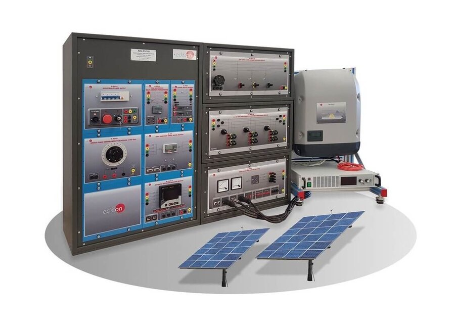
PL-911158
The purpose of this application is the study of photovoltaic power plants in the context of microgrids. It consists of a three-phase inverter fed with a photovoltaic panel array simulator. The user will be able to set the generation parameters and functions for the photovoltaic simulator according to the scernarios and conditions meant to be studied.
At the same time, the user will be able to study significant concepts about photovoltaic installations such as the MPPT characteristic (maximum power point tracking), the limitation of the inverter power (derating), the efficiency of the inverter or the reactive energy generation. This application includes a network analyzer to measure in real time the energy produced by the photovoltaic power plant.
PRACTICAL EXERCISES TO BE DONE WITH THE UNIT
- Installation of photovoltaic power plants.
- Grid-connection of photovoltaic plants.
- Setting the P-V curves for power generation.
- Monitoring the power injection into the grid.
- Maximum power point tracking (MPPT).
- Limiting the inverter power (derating).
- Determining the inverter efficiency.
TENDER SPECIFICATIONS
Power plants can be acquired in two ways:
• As a complete power system, under the reference “AEL-MGP”, which includes all “PWP- ” power plants, the Fault Injection Kit 1, “FIJ-K1” and the Energy Manager and Data Acquisition Software, “EMG-SCADA”.
• Acquiring them individually according to the technical requirements of the user. This option always requires at least the reference Conventional Power Plant, “PWP-CE”.
The “PWP-PE” includes the following elements:
• PSPS/A. Advanced Panel Simulator Power Supply.
This power source allows carry out the programming of characteristics curves of photovoltaic panels.
Open-circuit voltage: 500 V.
Closed-circuit current: 10 A.
Power output: 1500 W.
• N-INV02. Three-Phase Grid Inverter Module 2.
DC circuit switch.
Ground voltage protection for bus terminals and photovoltaic.
Output DC voltage range: 250 - 1000 VDC.
Ouput voltage: 3 x 400 V/50 Hz.
Output power: 3000 W.
Integrated web server.
• N-EALD. Network Analyzer Module with Oscilloscope and Data Acquisition.
The network analyzer module allows fulfilling measurements, displaying and analyzing all the parameters of the AC electrical networks. It has an LCD screen and push-buttons for the navigation through the different menus. It includes specific software for monitoring current and voltage curves, harmonics display, tariffs programming, alarms programming and electrical parameters storage.
Features:
Multifunctional three-phase power meter:
Three-phase and single-phase voltage. Up to 690 VAC L-L.
Line and neutral nominal current: 10 A.
Active, reactive and apparent power.
Suitable frequencies: 25 Hz, 50 Hz, 60 Hz and 400 Hz.
Display of the V-I vector diagram.
Supply voltage: 85 - 265 VAC.
Energy quality control:
Current and voltage individual harmonics measurement. Up to the 40th harmonic.
Voltage and current THD, TDD and K-Factor.
Maximums and minimums display.
Waveforms display, 128 samples/sec.
Events and data storage:
Harmonics analyzer:
Voltage and current THD, current TDD and K-Factor, up to the 40th harmonic.
Current and voltage harmonic spectrum and angles.
Tariff programming:
Class 0.5S IEC 62053 - 22, active and reactive power in four quadrants.
Measurement of the total and per phase three-phase active, reactive and apparent powers.
Usage time, four energy/demand records of total tariffs.
Eight tariffs, four seasons and four types of days.
Automatic daily report of energy consumption maximums and minimums.
Communications:
RS - 485 communication port.
Additional recommended elements (Not included):
• PWP-WE. Wind Energy Power Plant.
• EMT7/1K. 3PH Squirrel Cage Motor, 1 kW (2 units).
Nominal power: 1100 W.
Nominal voltage: 3 x 230/400 VAC Δ/Y.
Frequency: 50/60 Hz
Number of poles: 2.
Speed: 2730 rpm.
Nominal current: 2.52/1.45 A.
• N-EALD. Network Analyzer Module with Oscilloscope and Data Acquisition.
The network analyzer module allows fulfilling measurements, displaying and analyzing all the parameters of the AC electrical networks. It has an LCD screen and push-buttons for the navigation through the different menus. It includes specific software for monitoring current and voltage curves, harmonics display, tariffs programming, alarms programming and electrical parameters storage.
Features:
Multifunctional three-phase power meter:
Three-phase and single-phase voltage. Up to 690 VAC L-L.
Line and neutral nominal current: 10 A.
Active, reactive and apparent power.
Suitable frequencies: 25 Hz, 50 Hz, 60 Hz and 400 Hz.
Display of the V-I vector diagram.
Supply voltage: 85 - 265 VAC.
Energy quality control:
Current and voltage individual harmonics measurement. Up to the 40th harmonic.
Voltage and current THD, TDD and K-Factor.
Maximums and minimums display.
Waveforms display, 128 samples/sec.
Events and data storage:
Harmonics analyzer:
Voltage and current THD, current TDD and K-Factor, up to the 40th harmonic.
Current and voltage harmonic spectrum and angles.
Tariff programming:
Class 0.5S IEC 62053 - 22, active and reactive power in four quadrants.
Measurement of the total and per phase three-phase active, reactive and apparent powers.
Usage time, four energy/demand records of total tariffs.
Eight tariffs, four seasons and four types of days.
Automatic daily report of energy consumption maximums and minimums.
Communications:
RS - 485 communication port.
• N-VVCA2K. 2 kW Motor Speed Controller Module.
ON/OFF switch.
Micro connector of 8 pins.
Supply terminals:
Supply: 400 VAC.
Supply terminals L1, L2, L3 and N from the module to the frequency variator.
Output connector.
Motor speed potentiometer.
• N-CAR19T3. Three-Phase Bench of Commutable Capacitors Module.
ON/OFF switch.
Power terminals:
Supply voltage: 230 VAC.
Manual switch to turn on and off the inductances.
Power voltage: 400 VAC.
Capacitors: 3 x (3 x 7) µF.
Three LED indicators.
Three input/output power terminals.
• N-ERP-PGC02. Turbine Protection and Control Module.
Automatic speed and voltage controller:
Enables to connect up to 16 electric generators in parallel-island with active and reactive power distribution and start/stop operation control depending on the load demand.
Enables to connect a generator in parallel with the grid.
It allows different switch control modes, such as opening, closing and synchronization.
Three-phase measurement of the grid and the generator voltage.
Three-phase measurement of the generator current and power.
Single-phase measurement of the grid current.
Protection system:
Generator: Maximum/minimum voltage (59/27), maximum/minimum frequency (81O/U), voltage asymmetry, detection of dead busbars, overvoltage (32), load unbalance (46), negative sequence power/reduced power (32R/F), overcurrent by defined curve (50/51), inverse time overcurrent (IEC255), measured ground fault (50N/51N), phase rotation, switches faults.
Network: Maximum/minimum voltage (59/27), maximum/minimum frequency (81O/U), vector jump, phase rotation.
Measurement terminals.
Output terminals for the connection to the lab grid.
2 mm terminals for monitoring the PWM regulation of the excitation and speed signals.
Three control switches to:
Start and stop the turbine.
Give permission to synchronize the generator with the grid.
Give permission to synchronize the generator with the national grid.
Two potentiometers to:
Adjust the set point for the generated active power.
Adjust the set point for the output voltage.
Emergency stop push button:
Two circuit breakers for operation in synchronization and island mode with indicator lights.
• PWP-HE. Hydroelectric Energy Power Plant.
• EMT7/1K. 3PH Squirrel Cage Motor, 1 kW.
Nominal power: 1100 W.
Nominal voltage: 3 x 230/400 VAC Δ/Y.
Frequency: 50/60 Hz
Number of poles: 2.
Speed: 2730 rpm.
Nominal current: 2.52/1.45 A.
• EMT6/1K. Independent Excitation 3 PH Synchronous Motor-Generator, 1 kW.
Nominal power: 1000 VA.
Power factor: 0.8.
Nominal output voltage: 3 x 400 VAC.
Frequency: 50/60 Hz.
Speed: 3000 rpm.
Nominal output current: 0.8 A.
Nominal excitation current: 5 A.
• N-VVCA2K. 2 kW Motor Speed Controller Module.
ON/OFF switch.
Micro connector of 8 pins.
Supply terminals:
Supply: 400 VAC.
Supply terminals L1, L2, L3 and N from the module to the frequency variator.
Output connector.
Motor speed potentiometer.
• N-ERP-PGC01. Generator Protection Relay Module.
Automatic speed and voltage controller:
Enables to connect up to 16 electric generators in parallel-island with active and reactive power distribution and start/stop operation control depending on the load demand.
Enables to connect a generator in parallel with the grid.
It allows different switch control modes, such as opening, closing and synchronization.
Three-phase measurement of the grid and the generator voltage.
Three-phase measurement of the generator current and power.
Single-phase measurement of the grid current.
Protection system:
Generator: Maximum/minimum voltage (59/27), maximum/minimum frequency (81O/U), voltage asymmetry, detection of dead busbars, overvoltage (32), load unbalance (46), negative sequence power/reduced power (32R/F), overcurrent by defined curve (50/51), inverse time overcurrent (IEC255), measured ground fault (50N/51N), phase rotation, switches faults.
Network: Maximum/minimum voltage (59/27), maximum/minimum frequency (81O/U), vector jump, phase rotation.
Measurement terminals.
Output terminals for the connection to the lab grid.
2 mm terminals for monitoring the PWM regulation of the excitation and speed signals.
Three control switches to:
Start and stop the turbine.
Give permission to synchronize the generator with the grid.
Give permission to synchronize the generator with the national grid.
Two potentiometers to:
Adjust the set point for the generated active power.
Adjust the set point for the output voltage.
Emergency stop push button:
Two circuit breakers for operation in synchronization and island mode with indicator lights.
• GEC-KIT-1. Generator Excitation Circuit Kit 1.
• N-AVR/P. Automatic Voltage Regulator Module.
Input voltage: 0 - 100 VDC.
Input for voltage regulation signal through PWM control.
Terminals for PWM signals monitoring.
Output voltage: 0 - 100 VDC.
DC ammeter for output current measurement, 0 - 4 A.
3-pin female connector for connection to the excitation input of a generator.
Fuse 5 A.
• N-TRANS04. Single-Phase Transformer Module 230 VAC/2x35 VAC, 300 VA.
230 VAC single-phase input terminals.
Terminals for a 70 VAC single-phase output.
Terminals for two 35 VAC single-phase outputs.
Two-position switch: 0 (open)/1 (closed).
Fuses:
Primary side: 2 A.
Secondary side: 5 A.
• N-SPAD01. Single-Phase AC/DC Converter Module 1.
0 - 230 VAC single-phase input terminals.
AC/DC rectifier.
DC output terminals.
Filter capacitor for voltage ripple reduction.
Bypass terminals for filter capacitor connection.
Fuse 5 A.
• HYDP-K1. Hydroelectric Pumping Kit 1.
• EMT7. 3PH Squirrel-Cage Motor.
Nominal power: 370 W.
Nominal voltage: 3 x 230/400 VAC Δ/Y.
Frequency: 50/60 Hz.
Number of poles: 2.
Speed: 2730 rpm.
Shaft height: 71 mm.
• FRENP. Magnetic Powder Brake.
Nominal torque: 5 Nm.
Maximum power dissipation: 100 W.
Maximum output current adjustment.
Operating modes “freewheel “ and “blocking”.
Nominal voltage: 24 VAC/VDC.
Maximum output current: 2 A.
Output load (resistor): 4 - 20 Ohms.
Maximum power consumed: 70 W.
Remote voltage control: 0 - 10 VDC.
Weight: 4 Kg.
• N-EALD. Network Analyzer Module with Oscilloscope and Data Acquisition.
The network analyzer module allows fulfilling measurements, displaying and analyzing all the parameters of the AC electrical networks. It has an LCD screen and push-buttons for the navigation through the different menus. It includes specific software for monitoring current and voltage curves, harmonics display, tariffs programming, alarms programming and electrical parameters storage.
Features:
Multifunctional three-phase power meter:
Three-phase and single-phase voltage. Up to 690 VAC L-L.
Line and neutral nominal current: 10 A.
Active, reactive and apparent power.
Suitable frequencies: 25 Hz, 50 Hz, 60 Hz and 400 Hz.
Display of the V-I vector diagram.
Supply voltage: 85 - 265 VAC.
Energy quality control:
Current and voltage individual harmonics measurement. Up to the 40th harmonic.
Voltage and current THD, TDD and K-Factor.
Maximums and minimums display.
Waveforms display, 128 samples/sec.
Events and data storage:
Harmonics analyzer:
Voltage and current THD, current TDD and K-Factor, up to the 40th harmonic.
Current and voltage harmonic spectrum and angles.
Tariff programming:
Class 0.5S IEC 62053 - 22, active and reactive power in four quadrants.
Measurement of the total and per phase three-phase active, reactive and apparent powers.
Usage time, four energy/demand records of total tariffs.
Eight tariffs, four seasons and four types of days.
Automatic daily report of energy consumption maximums and minimums.
Communications:
RS - 485 communication port.
• PWP-BE. Battery Energy Storage Power Plant.
• N-INV/HY. Hybrid Inverter Module.
Three-phase inverter.
Three-phase energy injection to the grid with battery charge control.
Terminals:
DC input.
AC three-phase ouput.
Nominal power: 2000 W.
Output voltage: 400 VAC.
Frequency: 50 Hz.
• BAT3. Lithium - Iron Phosphate Battery.
Long battery life.
Battery capacity: 2000 Wh.
• N-EALD. Network Analyzer Module with Oscilloscope and Data Acquisition.
The network analyzer module allows fulfilling measurements, displaying and analyzing all the parameters of the AC electrical networks. It has an LCD screen and push-buttons for the navigation through the different menus. It includes specific software for monitoring current and voltage curves, harmonics display, tariffs programming, alarms programming and electrical parameters storage.
Features:
Multifunctional three-phase power meter:
Three-phase and single-phase voltage. Up to 690 VAC L-L.
Line and neutral nominal current: 10 A.
Active, reactive and apparent power.
Suitable frequencies: 25 Hz, 50 Hz, 60 Hz and 400 Hz.
Display of the V-I vector diagram.
Supply voltage: 85 - 265 VAC.
Energy quality control:
Current and voltage individual harmonics measurement. Up to the 40th harmonic.
Voltage and current THD, TDD and K-Factor.
Maximums and minimums display.
Waveforms display, 128 samples/sec.
Events and data storage:
Harmonics analyzer:
Voltage and current THD, current TDD and K-Factor, up to the 40th harmonic.
Current and voltage harmonic spectrum and angles.
Tariff programming:
Class 0.5S IEC 62053 - 22, active and reactive power in four quadrants.
Measurement of the total and per phase three-phase active, reactive and apparent powers.
Usage time, four energy/demand records of total tariffs.
Eight tariffs, four seasons and four types of days.
Automatic daily report of energy consumption maximums and minimums.
Communications:
RS - 485 communication port.
• PWP-FE. Flywheel Storage Energy Power Plant.
• N-EALD. Network Analyzer Module with Oscilloscope and Data Acquisition.
The network analyzer module allows fulfilling measurements, displaying and analyzing all the parameters of the AC electrical networks. It has an LCD screen and push-buttons for the navigation through the different menus. It includes specific software for monitoring current and voltage curves, harmonics display, tariffs programming, alarms programming and electrical parameters storage.
Features:
Multifunctional three-phase power meter:
Three-phase and single-phase voltage. Up to 690 VAC L-L.
Line and neutral nominal current: 10 A.
Active, reactive and apparent power.
Suitable frequencies: 25 Hz, 50 Hz, 60 Hz and 400 Hz.
Display of the V-I vector diagram.
Supply voltage: 85 - 265 VAC.
Energy quality control:
Current and voltage individual harmonics measurement. Up to the 40th harmonic.
Voltage and current THD, TDD and K-Factor.
Maximums and minimums display.
Waveforms display, 128 samples/sec.
Events and data storage:
Harmonics analyzer:
Voltage and current THD, current TDD and K-Factor, up to the 40th harmonic.
Current and voltage harmonic spectrum and angles.
Tariff programming:
Class 0.5S IEC 62053 - 22, active and reactive power in four quadrants.
Measurement of the total and per phase three-phase active, reactive and apparent powers.
Usage time, four energy/demand records of total tariffs.
Eight tariffs, four seasons and four types of days.
Automatic daily report of energy consumption maximums and minimums.
Communications:
RS - 485 communication port.
• N-VVCA7K. 5.5 kW AC Motor Control Module.
Supply voltage: 400 VAC.
Nominal power: 7 kW.
PWM output voltage connections: Three-phases, 230 VAC.
Digital inputs control panel.
Analog inputs control panel.
Setting and visualization display of the machine parameters.
• FMG5K. 5 kW Flywheel-Motor Group.
Flywheel:
Weight: 30 kg.
Maximum recommended speed: 4000 rpm.
Three-phase squirrel cage motor:
Nominal power: 5 kW.
Nominal voltage: 3 x 230/400 VAC Δ/Y.
Frequency: 50/60 Hz.
Number of poles: 2.
Speed: 2730 rpm.
• N-ERC. Electrical Regeneration Control Module.
Module for electric regeneration.
Input and regenerative power with sinusoidal ands square current.
Adjustable input and regenerative power control.
Configurable control terminals.
• FIJ-K1. Faults injection Kit 1.
• N-ERP-MA01. Feeder Management Relay Module with Digital I/O Module.
This protection relay is used to test different short circuits in any point of the power system. This protection relay allows investigations into protection and monitoring of overhead lines, underground cables and feeders.
The connections are via safety sockets.
The main functions:
Four levels of phase instantaneous overcurrent element (50P).
Four levels of negative-sequence overcurrent element (50Q).
Four levels of residual overcurrent element (50G).
Four levels of neutral overcurrent element (50G).
Two levels of phase time-overcurrent element (51P).
Two levels of residual time-overcurrent element (51G).
Two levels of ground time-overcurrent element (51G).
One level of negative-sequence time-overcurrent element (51Q).
Phase to ground overvoltage (59G).
Phase to phase overvoltage (59P).
Negative-sequence overvoltage (59Q).
Residual overvoltage (59G).
Phase to ground undervoltage (27G).
Phase to phase undervoltage (27P).
Six levels of secure overfrequency (81O).
Six levels of secure underfrequency (81U).
Two levels of negative power flow with definite time delay (32).
Two levels of positive power flow with definite time delay (32).
Battery monitoring station.
Breaker wear monitoring.
Synchrophasor protocol.
Peak demand and demand metering.
Auto-reclosing.
Creating fault and disturbance records.
The connection to the experimental circuit is via current transformers with ratio to suit the inputs of the relay.
It allows an effective demonstration of the effect of current and voltage transformer ratio, connection and rating on protective relays.
Accuracy: +- 10 %. Current: 5 A (AC). Frequency: 50/60 Hz.
Operating time: (10 - 25) ms.
• N-PSM. Power Switch Module.
Power terminals:
Four input terminals (3PH + N).
Four output terminals (3PH + N).
Auxiliary contacts:
One NO contact.
One NC contact.
Two push-buttons to open/close the power switch and the auxiliary contacts.
Two 24 VDC control inputs.
Two 24 VDC voltage outputs.
• N-ERP-MF01. Digital Fault Simulator Module.
It allows injecting different single-phase, two-phase and three-phase faults, with or without impedance, at the desired point through the fault and line terminals.
Trip time potentiometer.
Ethernet connection: two communication ports for SCADA remote control.
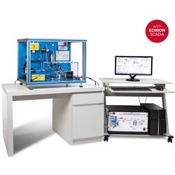
• EMG-SCADA. Energy Manager and Data Acquisition Software.
The SCADA stands for the operation and control center of the power plant. From this software, the user will control the power genereation resources. On the basis of this predefined planning, the power generation will injecte the available energy into the grid in order to meet the demand requirements. Meanwhile, the user will be able to visualize the power curves resulting from the power plant. All this energy production will keep a delicate balance with the energy consumption determined by the loads.
• All necessary cables to realize the practical exercises are included.
Cables and accessories, for normal operation.
Manuals:
This unit is supplied with the following manuals: Required Services, Assembly and Installation, Starting-up, Safety, Maintenance & Practices Manuals.
- Dimensions: 2000 x 320 x 920 mm approx. (78.73 x 12.59 x 36.22 inches approx.) - Weight: 150 Kg approx. (330 pounds approx.)
EXERCISES AND PRACTICAL POSSIBILITIES
1.- Installation of photovoltaic power plants.
2.- Grid-connection of photovoltaic plants.
3.- Setting the P-V curves for power generation.
4.- Monitoring the power injection into the grid.
5.- Maximum power point tracking (MPPT).
6.- Limiting the inverter power (derating).
7.- Determining the inverter efficiency.
Some practical exercises with the Energy Manager and Data Acquisition Software, EMG-SCADA:
8.- Remote control of voltage and power set points of the synchronous generator in the microgrid.
9.- Real time measurement of the synchronous generator electrical parameters.
10.- Remote synchronization operation with synchronous generator and grid.
11.- Remote control maneuvers for the different sources of renewable generation.
12.- Customized configuration of the wind speed curves.
13.- Automatic simulation of the pre-configured wind speed curves for a wind turbine with three-phase induction generator.
14.- Visualization of the power curve for the pre-configured wind speed values.
15.- Customized configuration of the solar irradiation curves.
16.- Automatic simulation of the pre-configured irradiation solar curves for the photovoltaic power generation.
17.- Visualization of the power curve for the pre-configured solar irradiation values.
18.- Visualization of the power curve for the hydroelectric generation.
19.- Visualization of the remaining capacity of the hydroelectric resource as the generated power is progressively delivered.
20.- Analysis of the efficiency and stability provided to the microgrid by the storage system during the simulation of a demand profile.
21.- Visualization of the demand and total generation curves to analyze the management of the different renewable resources during the simulated scenarios.
22.- Real time monitoring of frequency, current and voltage values and waveforms.
23.- Real time monitoring of the active, reactive and apparent powers generated.
24.- Visualization of the phasor diagrams of the system electrical parameters.
25.- Real time monitoring of the obtained results
26.- Data saving and storage.
27.- Comparison of the obtained results.
- Several other exercises can be done and designed by the user.
Optional
PWP-PE/ICAI. Interactive Computer Aided Instruction Software System:
This complete software package consists of an Instructor Software (EDIBON Classroom Manager - ECM-SOF) totally integrated with the Student Software (EDIBON Student Labsoft - ESL-SOF). Both are interconnected so that the teacher knows at any moment what is the theoretical and practical knowledge of the students.
- ECM-SOF. EDIBON Classroom Manager (Instructor Software).
ECM-SOF is the application that allows the Instructor to register students, manage and assign tasks for workgroups, create own content to carry out Practical Exercises, choose one of the evaluation methods to check the Student knowledge and monitor the progression related to the planned tasks for individual students, workgroups, units, etc... so the teacher can know in real time the level of understanding of any student in the classroom.
Innovative features:
• User Data Base Management.
• Administration and assignment of Workgroup, Task and Training sessions.
• Creation and Integration of Practical Exercises and Multimedia Resources.
• Custom Design of Evaluation Methods.
• Creation and assignment of Formulas & Equations.
• Equation System Solver Engine.
• Updatable Contents.
• Report generation, User Progression Monitoring and Statistics.
- ESL-SOF. EDIBON Student Labsoft (Student Software).
ESL-SOF is the application addressed to the Students that helps them to understand theoretical concepts by means of practical exercises and to prove their knowledge and progression by performing tests and calculations in addition to Multimedia Resources. Default planned tasks and an Open workgroup are provided by EDIBON to allow the students start working from the first session. Reports and statistics are available to know their progression at any time, as well as explanations for every exercise to reinforce the theoretically acquired technical knowledge.
Innovative features:
• Student Log-In & Self-Registration.
• Existing Tasks checking & Monitoring.
• Default contents & scheduled tasks available to be used from the first session.
• Practical Exercises accomplishment by following the Manual provided by EDIBON.
• Evaluation Methods to prove your knowledge and progression.
• Test self-correction.
• Calculations computing and plotting.
• Equation System Solver Engine.
• User Monitoring Learning & Printable Reports.
• Multimedia-Supported auxiliary resources.
What is this?
These percentage scores are an average of 0 user reviews. To get more into detail, see each review and comments as per below
If you have used this product, support the community by submitting your review