Aircraft Maintenance Trainer (AERO-MINI)
PL-552214
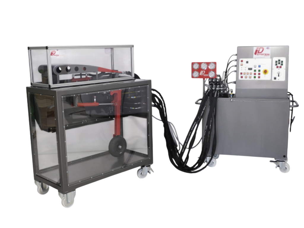
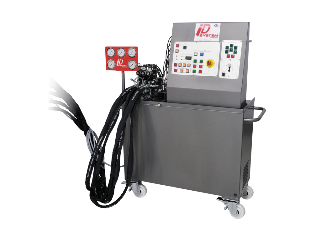
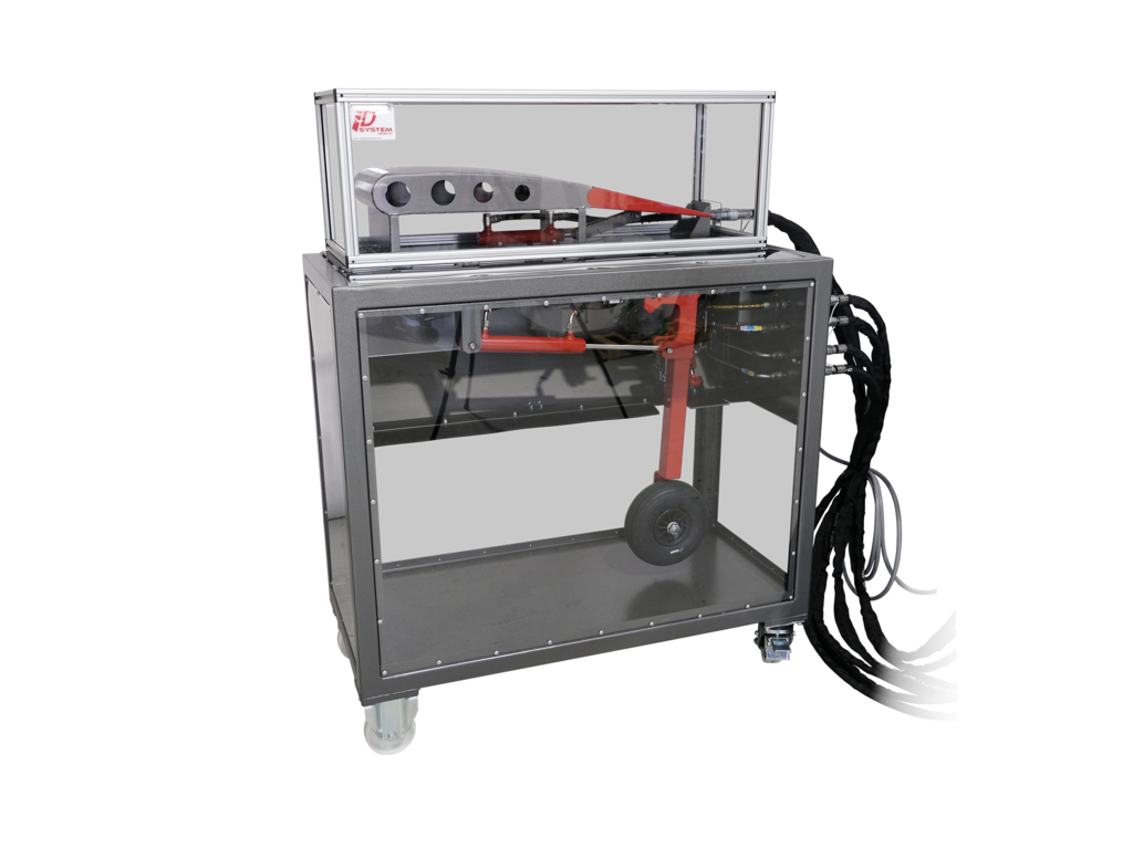
This equipment has been especially designed to put different level students/learners in the conditions of learning aeronautical hydraulics by associating hydraulic industrial technology components. We relied on the skills and experience of a teacher graduated from the French National Education and former mechanical engineer sailing in the French Air Force to develop this training equipment.
The educational goal is to identify the different components of an aeronautical hydraulic kinematic chain, to connect them hydraulically and electrically thanks to the different component modules and the electric power unit control while respecting the safety conditions essential to your profession. That is why we made the choice to protect the operating parts, double the hydraulic and electrical safeties as well as to protect the hoses from jet socks and anti-whip cables.
We have also created a black box, accessible only to the teaching staff, which makes it possible to trigger electrical failures on the circuits. A trouble shooting kit also makes possible to diagnose hydraulic failures at different places of the circuit. The bench provides the best conditions to learners to understand the technical specificities and the safety constraints related to the hydraulic aeronautics.
This equipment has been especially designed to put different level students/learners in the conditions of learning aeronautical hydraulics by associating hydraulic industrial technology components. We relied on the skills and experience of a teacher graduated from the French National Education and former mechanical engineer sailing in the French Air Force to develop this training equipment. The educational goal is to identify the different components of an aeronautical hydraulic kinematic chain, to connect them hydraulically and electrically thanks to the different component modules and the electric power unit control while respecting the safety conditions essential to your profession. That is why we made the choice to protect the operating parts, double the hydraulic and electrical safeties as well as to protect the hoses from jet socks and anti-whip cables . We have also created a black box, accessible only to the teaching staff, which makes it possible to trigger electrical failures on the circuits. A trouble shooting kit also makes possible to diagnose hydraulic failures at different places of the circuit. The bench provides the best conditions to learners to understand the technical specificities and the safety constraints related to the hydraulic aeronautics. Hydraulic power unit: Pump: • Fixed displacement gear pump 4,2 cm² • Flow: 6 l/min Motor: • Power: 1,5 kW • Single-phase; • Speed: 1500 rpm; • Voltage: 220 VAC; • Frequency: 50 HZ Tank: • Capacity: 22 L • Return filter: 15 µm • Integrated breather • Filling plug • Drain plug • Level indicator with thermocontact Hydraulic components: • Main circuit pressure relief valve: 80 bar • Auxiliary circuit pressure relief valve: 60 bar • Solenoid directional valve 4/2 by-pass with safety manual command Electrical cabinet: An electrical box with control panel fitted with a PLC controller, pad lockable switch disconnector and emergency stop. Hydraulic distribution: CETOP 3 Block including 5 stacks: - Stack 1 : 4/2 by-pass distributor and pressure relief valve with pressure tap on P – Main circuit - Stack 2 : 4/3 distributor and double one-way flow limiter with pressure tap on A and B – Control of the landing gear - Stack 3 : 4/3 distributor and double one-way flow limiter with pressure tap on A and B – Control of the door - Stack 4 : 4/3 distributor and double one-way flow limiter with pressure tap on A and B – Control of the flap Hydraulic connexion: 6 hoses 3/8” – 2 SN – Length 2 m with flat face female couplings and lock ring Electrical wiring: 7 wires DIN43650 Led and Harting plugs, Lg 1200mm Five pressure gauges to connect with the pressure tap and 5M 16x200 capillary hoses, length 1,500mm. Electrical specifications of the desk: a) Hydraulic power unit control : - Emergency OFF - White power indicator - Blue reset indicator - ON&OFF switch – green & red auxillary pump - ON&OFF switch – green & red main pump - Green safety switch - Red faulty temperature indicator b) Master and light test - Red master warning light/switch - Orange master caution light/switch - Light test switch c) Monitoring panel - Temperature Digital Display - Green Led LDG Door Up - Green Led LDG Door Down - Green Led LDG Gear switches Up - Green Led LDG Gear switches Down d) Warning panel - Red hydraulic warning indicator - Orange hydraulic caution indicator - Orange landing gear caution indicator - Orange flap caution indicator e) Hydraulic warning panel - Red main pump fault indicator - Orange low oil level indicator - Orange filter clogging indicator f) Front side electrical banner Landing gear& flap: - LDG gear lever up & down - 6 green position indicators for Landing gear - 2 Red indicators - Flap control 2 position switch g) Trouble Panel Box : access allowed only to teacher or trainers - Selector default coil LDG GEAR - Selector default coil LDG DOOR - Selector default coil FLAP - Selector default MAIN PUMP - Selector default LOW LEVEL - Selector default FILTER - Selector FIRST LDG INDICATION LIGHT - Selector SECOND LDG INDICATION LIGHT The operative part "Landing Gear" reproduces the same gear and trapdoor opening cycle kinematic as the majority of aircraft. The trapdoor opens thanks to a hydraulic cylinder and goes to find its blocking position, then the gear, also controlled by a cylinder, unfolds and to complete the cycle, the trapdoor closes itself. Sensors allow to validate or not the control of movement of the next step of the cycle. Technical description of the landing gear (POTA-V2): - 1 trapdoor operating double acting cylinder 32x20C50 - 1 operating double acting cylinder landing gear 32X20C200 - 4 dry contact sensors - 1 Harting supply cable towards PCA-V2 - 4 anti-pollution hydraulic couplings with 1 hoses kit (Length 3 m) This operative part is totally cased with Lexan protection panels. Dimensions of POTA-V2: - Lenght = 1250 mm - Width = 600 mm - Height = 1180mm A simple flap control system will be install on the top of the POTA-V2. This system will be made of a fixed part representing the wing profile (blue) and a mobile part representing the flap (orange). The flab move by a double acting cylinder control.
What is this?
These percentage scores are an average of 0 user reviews. To get more into detail, see each review and comments as per below
If you have used this product, support the community by submitting your review
CASE STUDIES
Aircraft Hydraulics and Landing Gear Training at Coleg Gwent
See how Coleg Gwent uses the AERO-MINI aircraft maintenance trainer from Edquip to teach hydraulics, landing gear operation and practical fault finding.


Challenge

Solution

Results


