Automotive Training Equipment
Sort by
Learn more about Automotive Training Equipment
In this section you will learn more about automotive education and training. We cover whish types of automotive teaching equipment and training systems exists, how they are used in classrooms and training centers, trends, and benefits of using automobile lab equipment.
What is Automotive Training?
Automotive training is the types of education which a person goes through to get the necessary skills to work with automobile maintenance and repair. The type and length of training necessary to work in an auto workshop differs by region and country. Places to get trained are vocational trade schools, community colleges, TVET colleges etc. alongside structured or unstructured apprentice programs.
Topics covered in Automotive Training Courses
The normal topics covered in automotive maintenance education and training courses:
Basic Automotive Maintenance & Service
In one of these foundational courses students learn to check different parts and systems of the vehicle, diagnose problems, and suggest solutions to avoid deterioration and assure safe operation. Typical topic fields are fuel, liquids, and electrical systems etc. These courses are typically taught in a technical workshop in a hands-on manner where the students get the benefits of kinesthetic or tactical learning.
Brake systems, Suspension & Steering
Automobile training classes associated to the chassis of a vehicle often cover brake systems, suspension & steering. Students learn to test, trouble shoot, diagnose and repair different types of problems in these systems through a hands-on manner. In these traditionally highly mechanical courses the students learn how to analyze sounds, looseness or unevenness, and to suggest improvements for repair or exchange of parts. Here a few links to subcategories of automotive breaks training equipment, or suspension & steering training equipment.
Automotive HVAC
Climate controls in automobiles are essential for a comfortable travel experience, which is why automotive training courses include HVAC essentials. The students learn how to read diagrams, trouble shoot and repair heating, ventilation and air conditioning systems in automobiles. Link to HVAC training systems.
Engine Performance & Repair
Automotive training courses in engine performance and repair teach students how to test an engine to ensure that it is running properly and with the desired efficiency. Learners will get trained to use different types of tools and diagnostics equipment to identify potential problems, as well as to disassemble an engine for exchanging parts before correct assembly. Here a few links to some subcategories of diesel engine training equipment or gasoline engine training equipment.
Hybrid & Battery Electric Vehicles
With the roll out of electric vehicles, automotive training courses also start including these systems into their training repertoire. These types of courses typically touch upon electric motors, diagnostics and maintenance of high voltage batteries and charging devices. Here is a link to such hybrid and electric vehicle training equipment.
Types of Automotive Training Equipment
Which types of automotive training equipment exists? Let us look at hardware solutions which provide a true hands-on experience for the students to get accustomed to industrial grade technology. There are four main types of training equipment, touching upon a much wider plethora of different topics.
Automotive Training Stands
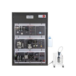
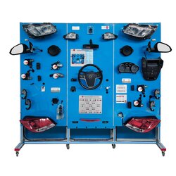
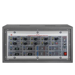
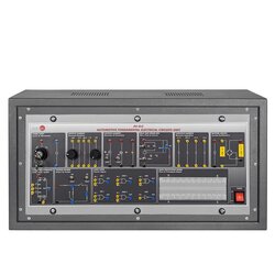
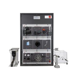
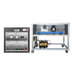
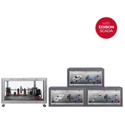
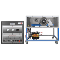
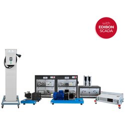
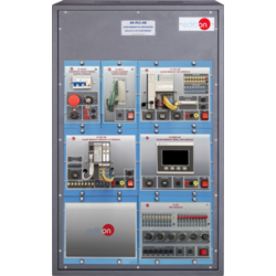
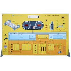
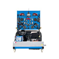
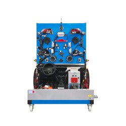
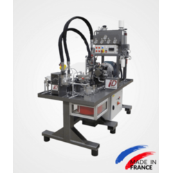
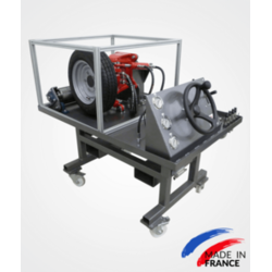
These types of training equipment are designed to explain complicated concepts and systems in an easier way. Training stands are built in a combination of original vehicle components applied to schematic boards or stands where students can understand how different parts are integrated and depend on each other. Students run tests and diagnostics in different operation modes, often with fault insertion by the trainer / educator to simulate common problems.
Working Engine Models
Working engine models for automotive training are essential tools and equipment for any classroom or training center. Every working engine model has its own uniqueness tied to which type of vehicle it is designed to power, it could be a gasoline or a diesel engine, for a small car or a large truck. The aim with a working engine model is to give students a learning experience in how different engines works, their integral parts and the most important dependencies.
Automotive Cutaway Models
Automotive cutaway models are used to teach how integrated mechanical systems work. They are normally done on a petrol or diesel engines, transmission systems, a gearboxes or any other complex automotive systems. Here is a link to a few automotive cutaway training models.
Functional Automotive Models
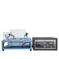
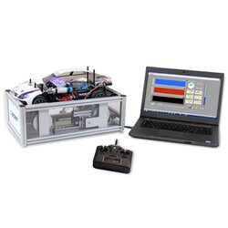
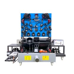
A functional automotive model is specifically designed to demonstrate how different systems work together in a real functional vehicle. These didactic equipment’s are significantly more complex than a training stand since students learn how different systems work together an impact each other. Link here to examples of automotive functional models for training.
Benefits of using Automotive Training Equipment
There are various types of benefits to using Automotive Training Equipment and hands-on learning systems when teaching students about automotive maintenance and repairs.
Content retainment
This is an important factor since educators frequently report about the experience that course materials seem to stick longer with learners when subjects are taught in a hands-on manner, rather than just out of textbooks.
Increased Engagement
Students are often of the opinion that it’s much more fun to learn when they get ownership of their own learning process and responsibility of their own skills attainment.
Critical Thinking
The main strain of thought in automotive training is that learners need to understand technology, be able to trouble shoot, diagnose and fix problems. This type of education and training requires a solution-oriented approach which favors critical thinking in learners, rather than just memorizing information.
Real World Experience
Working with industrial grade vehicle components and diagnostic tools prepares students for their future workplace in a way that textbooks cannot do. Furthermore, having an instructor guiding the use of training systems has proven influential in the preparation of the future workforce.
Workplace safety
Most accidents in the workforce generally comes from improper and untrained usage of equipment and machines, which is why its very important for students to familiarize themselves with safe operation of machines and tools already before entering the workforce.
Trends in Automotive Training Equipment
Most automotive training equipment is hands-on hardware equipment with or without some software components which goes alongside user manuals and some teacher and student content.
E-learning
Although most technical education and training is still better performed in a hands-on manner, training centers and relevant equipment might not always be available or accessible (think Covid impact) or students might want to enhance their lab-trainings with on-the-go e-learning solutions. Thus e-learning for technical training is a growing segment, mostly to be used as a complementary solution to a real hardware laboratory.
Augmented & Virtual Reality (AR & VR)
The last few years has shown an increasing interest from educational institutions to supplement their technical training centers with AR & VR solutions. Since the student gets into a much more immersive experience with VR than with e-learning this seems like a technology which in the longer run might have more of a fighting chance to compete with full blown real learning laboratories.
Who uses Automotive Training Equipment?
Automotive training equipment and learning systems are mostly used by teachers, trainers and educators in formal education, informal training institutes and corporate training departments.
Schools
Automobile training systems are sometimes used as early as in some technical middle schools but are more common in technical and vocational career paths in high school.
Colleges & Polytechnics
It is common that community colleges or TVET colleges offer both formal education and adult education, what we today have started calling lifelong learning. In such institutions one can get anything from diplomas and certificates to associate degrees or bachelor’s degrees in automotive technology, repair and maintenance.
Corporate Training Departments
Almost all the largest manufacturing companies worldwide have corporate training centers where they train their hires on technology, processes and tools in order to upskill or reskill their workforce.
How to find the best Automotive Training Equipment
The best way to find suitable automotive teaching equipment for your classroom or training center is to use a digital marketplace such as Edquip.
If you want to learn more about the benefits of using Edquip, read a bit more about Edquip for Customers.
